


March 03, 2017
WDM (Wavelength Division Multiplexing) is a method of transmitting data from different sources on a single fiber whereby each data channel is carried on its own unique wavelength. A WDM system uses a multiplexer at the transmitter to join various signals together, and a demultiplexer at the receiver to split them apart. Coarse Wavelength Division Multiplexing (CWDM) and Dense Wavelength Division Multiplexing (DWDM) are both mature WDM technologies, using standardized ITU-T wavelengths. This article will make a comparison between them according to their corresponding characteristics and applications.
CWDM is currently well-positioned to help carriers maximize their network capacity in the access, metro and regional network segments. CWDM supports fewer wavelengths than DWDM, but is available at a fraction of the cost of DWDM. This makes CWDM attractive for areas with moderate traffic growth projections. Thus CWDM is the ideal choice for cost efficiently short-haul transmission in telecoms or enterprise networks. While DWDM is designed for long-haul transmission where wavelengths are packed tightly together, providing a high-capacity solution in telecom networks. Generally speaking, DWDM and CWDM are based on the same concept of using multiple wavelengths of light on a single fiber, but differ in the wavelengths spacing, number of channels and the ability to amplify the multiplexed signals in the optical space.
The major difference between them is that DWDM multiplexing systems are made for longer haul transmission, by keeping the wavelengths tightly packed. They can transmit more data over a significantly larger run of cable with less interference than a comparable CWDM system. CWDM cannot travel long distances because the wavelengths are not amplified, and therefore CWDM is limited in its functionality over longer distances. Therefore, DWDM technology is one of the best choices for transporting extremely large amounts of data traffic over long distance in optical networks.
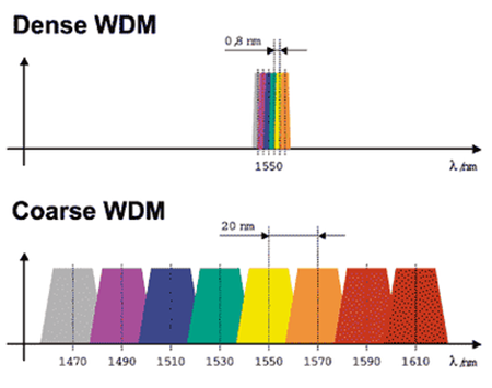
Compared with DWDM which is a more tightly packed WDM system, CWDM has larger wavelengths spacing with fewer wavelengths be transported on the same fiber. For instance, CWDM typically has 20 nm wavelengths spacing while DWDM typically has approximately 0.8 nm, hence can pack 40 plus channels compared to CWDM in the same frequency range. Thus, more channels and higher capacity can be achieved using DWDM.
CWDM systems, on the other hand, use DFB lasers that are not cooled. These systems typically operate from 0 to 70°C with the laser wavelength drifting about 6 nm over this range. This wavelength drift, coupled with the variation in laser wavelength of up to ±3 nm (due to laser die manufacturing processes), yields a total wavelength variation of about ±12 nm. However, DWDM systems require larger cooled DFB lasers for a semiconductor laser wavelength drifts about 0.08 nm/°C with temperature. The use of uncooled lasers causes lower energy consumption, which has positive financial implications for systems operators. For instance, the cost of the battery is minimized with the decreasing of energy consumption, which reduces operating costs. So DWDM systems are more expensive than CWDM systems for the application of cooled lasers.
In conclusion, CWDM and DWDM differ in complexity, offered capacity, cost and the markets they address. Due to its low cost and simple deployment, CWDM is a good fit for access networks and many metro/regional networks. While DWDM increases the distances between network elements, which is a huge benefit for long-haul service providers looking to reduce their initial network investment significantly.
Posted by: jowang at
08:57 AM
| Comments (2)
| Add Comment
Post contains 561 words, total size 4 kb.
February 17, 2017
Not all Ethernet cables are created equally. They are grouped into sequentially numbered categories ("catâ€) based on different specifications. Cat 5e, Cat 6, Cat 6a, Cat 7 cable are the most common kinds of Ethernet cables. How to tell the difference between them and choose the suitable one for your network?
First and foremost, let’s have a rough sketch of their characteristics. All network cabling consists of 8 wires; twisted, and made into 4 pairs, each color coded by a solid color with their respective dashed/striped white cables. Cat 5 cables are designed to support theoretical speed of between 10 Mbps and 100 Mbps. The Cat5e cable has lower crosstalk and provide a faster, reliable and steady speed than Cat 5 cable. Cat6 cables have more stringent specifications than Cat 5e cables and are capable of supporting 10 Gbps. They have slighter thicker wires, and the cores are more tightly twisted together. Cat 7 cables feature even more strict specifications for crosstalk and system noise than Cat 6. And shielding have been added for individual wire pairs on the Cat 7 cables. Here are some factors to consider when choosing these kinds of Ethernet cables.
STP (shielded twisted pair) cables simply have additional shielding material that is used to cancel any external interference that may be introduced at any point in the path of the cable. UTP (unshielded twisted pair) cables have no protection against such interference and its performance is often degraded in its presence. But both of them have interference canceling capacities.
Typically, using STP cables ensures that you can get the maximum bandwidth from your cabling even if the external condition is less than ideal. STP cables work by attracting interference to the shield, then running it off into a grounded cable. If the cable is improperly grounded, then its noise-canceling capabilities are severely compromised. Additionally, STP cables have bigger diameter than UTP cables, and they are more expensive. Besides, they are more fragile as the shield must be kept intact to ensure them work properly. STP cables are commonly used in industrial settings with high amounts of electromagnetic interference, such as a factory with large electronic equipment, where they can be properly installed and maintained. They can also be used in outdoor environments where the cables are exposed to the elements and man-made structures and equipment that may introduce additional interference.
UTP cables are smaller than STP cables, which makes them easier to install, particularly in bulk or in narrow spaces. They do not require the presence of a grounding cable and do not require much maintenance, but transmit data as fast as STP cables. Generally, UTP cables are more prone to noise than properly installed and maintained STP cables. They are more prevalent and popular used in domestic and office Ethernet connections, and in any area where there is not a high degree of electromagnetic interference.
Both solid and stranded Ethernet cables refer to the actual copper conductor in the pairs. The solid cable uses one solid wire per conductor, so in a standard Cat 5e or Cat 6 four pair (8 conductor) roll, there would be a total of 8 solid wires. Stranded cable uses multiple wires wrapped around each other in each conductor, so in a 4 pair (8 conductor) 7 strand roll (typical configuration), there would be a total of 56 wires.
Solid cables are most useful for structured wiring within a building. They can be easily punched down onto wall jacks and patch panels as they have only one conductor. The wire seats properly into insulation displacement connector. Solid cables are less useful when you are terminating with standard RJ45 connectors, as used when making patch cables. Most RJ45 connectors use 2 prongs which penetrate the conductor itself. This is not desirable, since solid cable has the tendency to break when penetrated by the prong. Using a 3 prong style RJ45 connectors creates a much better connection as it doesn’t break the conductor—the 3 prongs style connection wraps around the conductor instead of penetrating it. It is recommended that stranded network cable be used for patch cables as they make better quality RJ45 termination connections than even using 3 prong connectors.
Stranded cables are much less useful for punching down on wall jacks because the strands do not keep their perfect round shape when thrust into a insulation displacement connector. For best results, use solid for wall jacks and stranded for crimp connectors. Stranded cable is typically used to create patch cables. The cable itself is more flexible, and rolls up well. The RJ45 terminators have a better, and more flexible and complete connection to stranded wires than solid wire.
From this article, you can make a clear identification of Cat5e, Cat6, Cat6a, Cat7 cables. When you plan to purchase Ethernet cables, you need to consider their differences like shielding, transmission distance, cost, durability, etc. Hope this post would help you choose the suitable cable and build a high performance network.
Posted by: jowang at
06:48 AM
| Comments (3)
| Add Comment
Post contains 844 words, total size 6 kb.
February 16, 2017
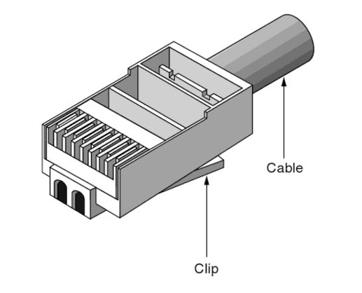
RJ45 modular jack is used for mounting optical connectors into the wall plate or patch panel for network wiring installs. There are numerous requests for wiring diagrams or general information on how to punch down or terminate keystone jacks (Cat5e / Cat6) after running your telecom network's cross-connect cabling. Building a patch cable involves installing RJ45 plug connectors on each end of a stranded cable. Here we describe the process of installing the RJ45 connectors.
Attaching cable connectors involves the use of very sharp knives for stripping cable insulation as well as crimping tools that can be dangerous to operate. Many crimping tools incorporate a ratchet mechanism that, once engaged, prevents the tool from being opened until it has first closed completely. Anything caught in the crimping tool, including your fingers, will be crushed.
Cut cable to needed length. Remove the outer jacket of the cable using the Cable Prep Tool. Place the tool approximately 1.5†from end of the cable. Rotate tool at least twice around the cable, both clockwise and counter-clockwise. That will score the jacket allowing you to remove it without damaging the conductors inside the jacket.
Carefully strip away a few inches of the outer insulation from the twisted-pair cable, revealing the individually insulated twisted-pair conductors inside. Each twisted-pair conductor consists of a set of thin stranded wire surrounded by insulation. Do not cut the insulation of the twisted-pair conductors.
Orient the conductors according to the colors of the insulation. Pull the wire braid back over the outer jacket. Trim off the clear plastic jacket.
Straighten out the twisted-pair conductors, arrange them and cut the conductors to a length about 12mm. Leave the insulation in place on the individual twisted-pair conductors. Make sure that the conductors are all cut to the same length, providing a square end to the cut. Untwist and separate all of the conductor pairs.
TIP: Use the jacket that was just removed and feed each conductor down the jacket to untwist it. Bonded twisted pair cable can be separated using a 1797B cable separator.
Use the outer edge of the cable scissors to straighten conductors. Using gentle pressure (to avoid damage to the conductors), put each conductor between thumb and edge of cutter and pull up from outer jacket to end of the conductor.
Bring the sorted conductors together, holding tightly between the thumb and forefinger. Recheck to ensure the wiring sequence is correct. Cut the wires at a 90º angle about 1/2†from the end of the jacket.
Insert the conductors into the plug. Hold the plug with the copper contacts facing up and the locking tab facing down. In this position, the orange/white conductor should be the first conductor on the left. Insert the conductors into the plug. Make sure the drain wire is wrapped around the jacket underneath the back of the plug prior to crimping in order to complete the ground.
Crimping the plug using the cable crimping tool. Place the plug into the crimp tool and squeeze handles tightly. The copper splicing tabs on the plug will pierce into each of the eight conductors. The locking tab will cinch onto the outer jacket of the cable.
Remove plug from tool. Check the conductor sequence and ensure outer jacket is inside the plug and secured by the locking tab. Trim excess drain wire just below entry into plug.
Repeat steps for other end of cable. Then use a cable tester to ensure proper installation and wiring of plugs.
Posted by: jowang at
02:59 AM
| Comments (1)
| Add Comment
Post contains 614 words, total size 5 kb.
February 13, 2017
The deployment of fiber optics in telecommunications and wide area networking has been common for many years, but more recently fiber optics have become increasingly prevalent in industrial data communications systems as well. Fiber optic technology uses pulses of light to carry data along strands of glass or plastic. It's the technology of choice for the government's National Broadband Network (NBN) and data centers, which promises to deliver next-generation 200G and 400G Ethernet speeds.

When talking about 'speed', we were actually talking about throughput (or capacity) — the amount of data you can transfer per unit time, says Associate Professor Robert Malaney from the University of New South Wales, School of Electrical Engineering and Telecommunications.
And fiber optics can definitely transfer more data at higher throughput over longer distances than copper wire. For example, a local area network using modern copper lines can carry 3000 telephone calls all at once, while a similar system using fiber optics can carry over 31,000.
So what gives it the technical edge over copper wires? Traditional copper wires transmit electrical currents, while fiber optic technology sends pulses of light generated by a light emitting diode or laser along optical fibers.
In both cases you're detecting changes in energy, and that's how you encode data. With copper wires you're looking at changes in the electromagnetic field, the intensity of that field and perhaps the phase of the wave being sent down a wire. With fiber optics, a transmitter converts electronic information into pulses of light — a pulse equates to a one, while no pulse is zero. When the signal reaches the other end, an optical receiver converts the light signal back into electronic information.
The throughput of the data is determined by the frequency range that a cable will carry — the higher the frequency range, the greater the bandwidth and the more data that can be put through per unit time. And this is the key difference — fiber optic cables have much higher bandwidths than copper cables (eg. cat5e copper cable).
"Optical fiber can carry much higher frequency ranges — note that light is a very high frequency signal — while copper wire attenuates or loses signal strength at higher frequencies," says Malaney.
Also, fiber optic technology is far less susceptible to noise and electromagnetic interference than electricity along a copper wire.
"You can send the signal for over 200 km without any real loss of quality while a copper cable signal suffers a lot of degradation over that distance," says Malaney.
As well as a significant increase in connection speed, fiber optic networks offer a tremendous capacity to keep up with any new technological advances. Once the basic fiber optic infrastructure is in place, it can be rearranged and the end point electronics upgraded when necessary, to deliver even higher capacity. It can do this far more effectively than existing wireless or copper based systems.
In terms of its serviceable lifetime, glass (from which fiber optic cable is made) is long lasting, stronger than copper and more able to retain its transmission properties after physical stress such as weight strain, or even attack by rats and cockatoos. We install fiber differently from copper: in good quality coatings, inside ducts, or in the case of newer systems, encased entirely by electrical transmission wires.
For applications where signal security is a concern, fiber optic technology is an excellent solution. Fiber optic cables do not generate electromagnetic fields that could be picked up by external sensors. It is also more difficult to 'steal' signals by spicing into optical fibers than it might be with conventional copper wiring.
Posted by: jowang at
08:48 AM
| Comments (1)
| Add Comment
Post contains 611 words, total size 5 kb.
February 06, 2017
Have you ever wired a cable directly into a piece of hardware? Some equipment in the past years provided terminals or termination blocks so that cable could be wired directly into a direct component. At the ends of the cables you install, something must provide access and transition for attachment to system electronics. Thus, you need connectors.
Connectors usually have a male component and a female one, except in the case of hermaphroditic connectors such as the IBM data connector. Jacks and plug are usually systematically shaped, but sometimes they are keyed, which means that they have a unique, asymmetric shape or some system of pins, tabs and slots that ensure that the plug can be inserted only one way in the jack. This article covers three types of connectors you may encounter when working with structured cabling system.
Many people in the cabling business use twisted-pair connectors more than any other type of connector. The connectors included the modular RJ types of jacks and plugs and the hermaphroditic connector employed by IBM that is used with shielded twisted-pair cabling (ie. cat6 shielded cable). What is equally important as the cable connector is the connector used with patch panels, punch-down blocks, and wall plates; this connector is called an IDC (insulation displacemeny connector).
Most unshielded twisted-pair (UTP) and screened twisted-pair (ScTP) cable installations use patch panels and, consequently, 110-style termination blocks. The 110-block contains rows of specially designed slots in which the cables are terminated using a punch-down tool.
Solid vs. Stranded Conductor CablesUTP and ScTP cables have either solid copper conductors or conductors made of several tiny strands of copper. Solid conductors are very stable geometrically and therefore electrically superior, but they will break if flexed very often. Stranded conductors are very flexible and resistant to bend-fatigue breaks, but their cross-sectional geometry changes as they are moved, and this can contribute to electrical anomalies. Stranded cables also have a higher attenuation than solid-conductor cables.
The differences in conductors mean a difference in IDC types. You have to be careful when purchasing plugs, wall plates, and patch panels because they won’t work interchangeably with solid- and stranded-core cables because the blade designs are different.
Twisted-pair cables are most commonly available as UTP, but occasionally, a customer or environmental circumstances may require that ScTP cable be installed. In an ScTP cable, the individual twisted pairs are not shielded, but all the pairs collectively have a thin shielded around the shielded of foil around them. Both UTP and ScTP cables use modular jacks and plugs. For decades, modular jacks have been commonplace in the home for telephone wiring.
Modular connectors come in four-, six-, and eight-position configurations. The number of positions defines the width of the connector. However, many times not all of the positions have metal contacts installed. Make sure that the connectors you purchase are properly populated with contacts for your application. Note the metal shield around the jack; it is designed to help reduce both EMI emissions and interference from outside sources, but it must be connected properly to the cable shield to be effective. The following figure shows an eight-position modular plug for UTP cable.
Shielded twisted-pair connectors go with the shielded twisted-pair cable which encases the signal-carrying wires in a conducting shield as a means of reducing the potential for electromagnetic interference. How effective the shielding is depends on the material used for the shield--its thickness and frequency, the type of electromagnetic noise field, the distance from the noise source to the shield, any shield discontinuity and the grounding practices. Please note that the crosstalk and signal noise can increase if the effects of the shield are not compensated for.
Posted by: jowang at
03:50 AM
| No Comments
| Add Comment
Post contains 627 words, total size 5 kb.
January 22, 2017
Ethernet represents the plumbing pipes of the Internet. Many network installers are familiar with Cat5e and Cat6 cables with RJ45 connectors. But the term "Ethernetâ€, co-invented by Robert Metcalfe, encompasses an entire range of twisted pair and fiber cables that are constantly being upgraded and standardized by the Institute of Electrical and Electronics Engineers known as IEEE. Each new iteration of Ethernet, or category, supports increasingly faster bandwidth speeds.

Cat3 cable is an earlier generation of Ethernet but can still be seen in older deployments. With the ability to support a maximum frequency of 16 MHz, this type of Ethernet can still be used for two-line telephone systems and 10BASE-T networks. CAT3 cable can also be used for alarm system installation or similar applications. CAT3 cable can have 2, 3, or 4 copper pairs (though uncommon). Category 5e cable however, has become the default Ethernet category of choice with the ability to support faster speeds and frequencies.
Cat5 Ethernet, introduced 10/100 Mbps Ethernet, also known as Fast Ethernet. Even though some older deployments still use CAT5 cable, it is now considered obsolete and has since been replaced by Cat5e.
Although Cat5 and Cat5e cables are physically similar, Category 5e Ethernet adheres to more stringent IEEE standards. Cat5e is the most common type of cabling used for deployments due to its ability to support Gigabit speeds at a cost-effective price. Even though both Cat5 and Cat5e support a maximum frequency of up to 100MHz, Cat5e has completely replaced its predecessor. Gigabit Ethernet utilizes 4 data pairs in comparison to Fast Ethernet which utilizes 2 data pairs.
Cat 5e is perfectly fine. Many companies are placing more and more servers on the cloud. This means that if everything you do is on the cloud, and you require very little internal networking, your limiting factor will not be the type of cable, but the speed of your Internet. Quite likely, Cat 5e will achieve faster connections than your Internet speed, making Cat 5e the choice of most users.
Cat6 network cables have been around for only a few years less than Cat5E cables. However, they have primarily been used as the backbone to networks, instead of being run to workstations themselves. The reason for this (beyond cost) is the fact that, while Cat6 cables can handle up to 10 Gigabits of data, that bandwidth is limited to 164 feet — anything beyond that will rapidly decay to only 1 Gigabit (the same as Cat5E).
Cat6 wiring can support up to 10 Gbps and frequencies of up to 250 MHz. While Cat5e cable features 1.5-2 twists per cm, Cat6 cables are more tightly wound and feature 2 or more twists per cm. Cat6 cables also sport thicker sheaths compared to Cat5e. Though standard Ethernet supports distances of up to 100 meters, CAT6 cable only supports 55 meters when transmitting 10Gbps speeds. Even though Cat6 and Cat6a cabling offers higher performance rates, many LANs still opt for CAT5e due to its cost-effectiveness and ability to support Gigabit speeds. When transmitting at 10Gbps speeds, Cat6 cables only support a maximum distance of 37 meters.
Cat6a can support bandwidth frequencies of up to 500 MHz, twice the amount of Cat6 cable, and can also support 10Gbps like its predecessor. However, unlike Cat6 cabling, Cat6a can support 10 Gigabit Ethernet at 100 meters. Cat6a cabling on the other hand, can transmit the same speeds at up to 37 meters. Cat6a also features more robust sheathing which eliminates alien crosstalk (AXT) and improves upon the signal-to-noise ratio (SNR). The stronger sheathing makes Cat6a cabling considerable thicker than Cat6.
Cat7 can also support 10 Gbps, but laboratory testing has successfully shown its ability to transmit up to 40 Gb at 50 meters and even 100 Gb at 15 meters. The cabling can support frequencies of up to 600 Mhz. Cat7 offers extensive shielding to reduce signal attenuation and is relatively stiff in comparison to previous generations of cabling. The shielding needs to be grounded and Cat7 also requires special GigaGate45 (CG45) connectors.
Which type of Ethernet cable you should choose depends on your specific applications and requirements. When you plan to purchase Ethernet cables, you need to consider their differences like transmission distance, cost, durability, etc. Hope this post would help you choose the suitable cable and build a high-performing and future-proofing network.
Posted by: jowang at
09:51 AM
| No Comments
| Add Comment
Post contains 739 words, total size 6 kb.
January 20, 2017
Shielded CAT5e cable is generally referred to as STP CAT5e or Shielded Twisted Pair CAT5e. It is designed to defend against electromagnetic interference or EMI. EMI is also sometimes called radio frequency interference or RFI. EMI is simply the enemy of electrical communication. This interference radiates from electrical components and prevents electrical current from flowing properly. In the case of CAT5e cable this can often result in a partial or complete loss in communication. A partial loss will often be seen by a user as a very slow connection. This is because if some of the data is not transmitted properly the sending equipment must resend it until it is correct, making the time required to transfer data increased. The equipment may not be able to establish a connection or if they do, it may get dropped part way through the data transfer.
Other times the interference may be too much, resulting in a near complete loss of signal where no data can be transmitted correctly. In this case the equipment generally will not be able to even establish a connection to begin communication.
There are a lot of things around us all the time that can and do cause varying degrees of EMI like power lines, electric motors, fluorescent lights, thermostats, and electrical circuits which are found in just about everything these days. Even things as common as elevators, air conditioners, and microwaves cause electromagnetic interference. These days so many appliances, motors, common devices found around the house, and much more in the office or industrial setting cause EMI, that it is often very difficult to narrow down what could slow down your network.The amount of EMI from these devices can vary due to many factors, but they can be a problem for your ethernet connections if not properly protected.
An installation of unshielded CAT5e cable run over fluorescent lights can result in a complete loss of signal in your cable. Running it past electric motors or near high power equipment can result in problems whenever those things are being used.
If you're in any situation where you want to make sure that you get the most speed and efficiency out of your network, you'll probably want to use shielded CAT5e cable. It's hard to know when and where you'll run into enough EMI to cause a problem, but if you use shielded CAT5e cable in the first place you won't have to worry about tearing the cable from the wall to replace it if you do run into that problem.
Making sure your network operates properly is especially important in your business or office building, but can also be just as important to you on your home network.
Shielded CAT5e cable is generally referred to as STP CAT5e or Shielded Twisted Pair CAT5e. This term, however, is used to refer to many different styles of shielding. The most common type of shielding uses what is called a screen. This screen is a metal covering that goes around the entire set of 8 wires found in CAT5e cable. This can be done by a single solid foil wrap around the wires, braided strands of cable wrapped around all the wires, or a combination of the two. This type of cabling is very effective at blocking any EMI that could cause problems in most installations.
If you want to ensure the proper operation of your network, we would recommend using STP cable like this for all in wall and other critical runs of cable. This way you can rest easy knowing you’re getting the most speed that you can out of your network.
You do, in fact, need to use shielded RJ45 connectors to get the full benefit of STP cable since EMI can effect any and every square millimeter of your cable.
Posted by: jowang at
02:29 AM
| No Comments
| Add Comment
Post contains 674 words, total size 5 kb.
January 06, 2017
When it comes to Ethernet cables, we often hear people ask what’s the difference between Cat5e, Cat6, and Cat6a cable? The most obvious similarity is that all of them use RJ-45 connector to plug into Ethernet jackets with their respective specifications. But what’s the difference between them? The following part will focus on this point.
Cat5e Ethernet cable is an enhanced version of Cat5 cable. It was made to support 1000 Mbps "gigabit" speeds up to 328 feet, so in theory, it's faster than Cat5. Cat 5e is measured and rated at 100MHz. It it also cut down on crosstalk and the interference you can sometimes get between wires inside the cable. It means that you're more likely to get fast, reliable speed out of Cat5e cabling compared with Cat5 cabling.

Cat 6 cables have been the standard in cabling for a while now for high-speed gigabit Ethernet networks. They support the high speeds required by the 10G Ethernet standard. However, that support is limited to approximately 164 ft, after that the ultimate speed is the same as Cat5e. The frequency in the Cat6 cables jumps up to 250 MHz making it far superior to the 100 MHz in the Cat5e.
In addition to the increased speed, Cat6 cables have a tighter twist in the cables allowing for two-way communication. The higher standard support has also been known to eliminate some or all crosstalk with other cables.
This is the most recent and one of the most advanced of the Ethernet Cables, which provides the same 10Gbps speed but for a total of 330 feet. Cat 6A cables are an improvement to first generation Category 6 cables, the "A†standing for augmented. These cables deliver lightning fast speeds making them suitable for 10G networks and high bandwidth needs. They also have double the amount of frequency of Cat 6A to a total of up to 500 MHz.
It's worth noticing that your network speed is different to your internet speed. Chances are upgrading your cables isn't going to make a difference in how fast you load the web page — your internet speeds are still much slower than speeds on your network. However, if you're transferring files between computers with gigabit-compatible hardware can make things move along faster. Remember, you'll need more than just cables — to get gigabit speeds, you'll also need a gigabit-compatible router and gigabit-capable network cards in your computers. Most modern routers and cards are already capable of these fast speeds, but if you have any older PCs or routers, they might not be. Google your hardware's model number to find out.
If you're happy with the current speeds on your network, then there's no need to go through the trouble of upgrading everything. However, if you have gigabit-capable hardware already, then upgrading the cables is very cheap. If you're looking to get the best possible speeds out of your network, upgrading the old Cat5 cables to Cat5e could help. Like what was mentioned above, some Cat5 cables can reach gigabit speeds, but unless you want to run speed tests and find out — which sounds horribly tedious to me — you might as well just spend a few bucks and get all Cat5e or Cat6. If you're running these cables through your walls instead of just through your office, though, it's going to get more costly (and less worth the trouble).
Lastly, remember that when we talk about the speeds of these cables, those are all theoretical. Even if everything on your network supports gigabit ethernet, you'll probably never see speeds of 1Gb/s. But, your data transfers will be a lot faster than they would on non-gigabit hardware. Also, if you're running cable throughout your house, you may notice a decrease in speeds if you are using cables longer than 100m.
In general, most of the time Cat5e is fine for most networks but keep in mind your network is as strong as your weakest link. If you do need faster performance or see yourself needing it in the future your best bet is to invest in Cat 6 to help future-proof your network.
Posted by: jowang at
04:13 AM
| Comments (2)
| Add Comment
Post contains 710 words, total size 5 kb.
December 22, 2016
The last few decades have seen the broad adoption of fiber optic transceivers used in optical communications for both telecommunication and data communications applications. However, would the copper connectivity withdraw from the market? Copper medium usually doesn’t require any transceivers, as they are part of the interface module. However, in order to cut down expenditures, some vendors use SFP copper transceiver with an RJ-45 female connector for Gigabit Ethernet connectivity over copper medium, or XFP copper transceiver for 10Gigabit Ethernet (10GbE) connectivity over CX4 copper. This article will give you a complete guide to these copper transceivers.
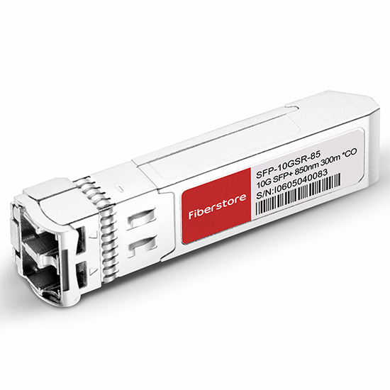
Supporting 10/100/1000 Mbps data-rate in excess of 100 meters (325 feet) reach over UTP Category5/5e cables, copper transceiver module is ideally suited for implementing small form-factor Network Interface Cards (NICs) and uplinks. As such, it is highly appropriate for use in high-density applications such as LAN 1000BASE-T, switch-to-switch interfaces, switched backplanes, blade servers, gaming devices, and router/server interfaces.
With the development of 1000BASE-T technology, 1000BASE-T and 100BASE-TX copper SFP transceiver over Category 5 copper cabling is an attractive option for network. The advantages are listed as follows:
- For 100m reach over Cat 5 UTP cable
- Hot-pluggable SFP footprint
- Supports RX_LOS as link indication function
- Fully metallic enclosure for low EMI
- Low power dissipation (1.05 W typical)
- Compact RJ-45 connector assembly
- Compliant with SFP MSA and IEEE Std 802.3-2002
As a kind of copper XFP transceiver, the XFP 10GBASE-CX4 module uses a CX4 connector to provide a connection to up to 15 meters over CX4 grade copper cable. Transparently to the user, the module transfers the 10GbE data stream over four full-duplex 3.125 Gbps channels over a single parallel copper cable. The product offers the ability to scale bandwidth in 10G increments, and directly with the industry standard MDI electrical socket.
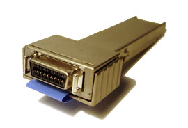
CX4 is an extension of the four-channel 10 Gbps XAUI interface and is available in 70-pin MSA transponder modules, otherwise known as Xenpak, XPAK and X2. The 10GBASE-CX4 solution employs an Infiniband-style Twin-AX cable (click to see the Cisco 10G twinax). In this case, eight 100-ohm differential Twin-AX cables are bundled into a single outer shield. The center conductors are 24 AWG wire for compatibility with printed circuit board termination inside the connector housing. The limitation of the 10GBASE-CX4 solution is that it requires a 70-pin MSA socket and only supports the IEEE802.3ae 10GE data format.
The XFP format also offers the distinct feature of being data agnostic, which opens the market for the copper based solution to telecommunications applications as well. The 10 Gbps serial solution over copper adds the final link option to the XFP industry, offering everything from the ultra low-cost sub-20m 10 Gbps shelf-to-shelf and rack-to-rack links to 80 km or longer optical links.
Among the above-mentioned copper transceivers, what must be noticed is that copper SFP transceiver offers a flexible and simple method to be installed into SFP MSA compliant ports at any time with no interruption of the host equipment operation. It enables for seamless integration of fiber with copper LAN connections wherever SFP interface slots can be found. Such system is economical, it saves time, offers flexibility and eliminates the necessity for replacing entire devices once the customers have to change or upgrade fiber connections and you will benefit so much from it.
Posted by: jowang at
03:18 AM
| Comments (1)
| Add Comment
Post contains 551 words, total size 4 kb.
December 15, 2016
Customers for fiber optic cable installations usually require documentation of test results before accepting and paying for the work. Testing needs to be done carefully to ensure the measurements are accurate and reliable. A definitive repertoire of tests, known as the "essential six," can benefit the inexperienced system engineer. Six basic test procedures measure distance, fiber loss, event loss, link loss, event-return loss and link-return loss. These procedures are implemented at all four levels of fiber operation, including pre-installation, installation and acceptance, maintenance and restoration.
An OTDR can be used to accomplish the six test procedures. In addition, clean connections on the fiber media under test are imperative. All six test procedures will prove inaccurate or impossible to accomplish if the fiber-optic connectors are dirty.
The optical distance between one point and another depends on definition. For example, the distance could be the fiber-cable length between a transmitter and a receiver, or it could be the fiber-cable length between two splices. An OTDR is the test instrument used worldwide to measure optical test events either automatically or manually. Events are detected as disturbances in the OTDR's relatively linear trace display.

To measure optical distance between two points, the OTDR launches a laser-generated light pulse down the fiber at the transmission end of the cable. The instrument then detects the backscatter returned from the fiber and any reflections from shiny surfaces. It measures the time taken by the light pulse to make the round trip on the fiber and calculates that time into distance.
One minor deviation in this test is the difference between real and apparent distance. The optical, or apparent distance, is the distance reading registered on the OTDR, and is always longer than the real distance. One reason for the distance difference results from the undulation of fiber as it resides within loose-tube cable, which adds to its length. Another reason involves buried cable as it winds within a trench, thereby producing a longer optical length.
The backscatter trace is a representation of the fiber itself. The slope of the backscatter trace discloses that less and less light is being reflected back as the length of the fiber increases. This slope represents fiber loss, a manufacturer's specification. Typical fiber-loss measurements are given as the amount of light (in decibels) lost per kilometer. For example, a long-haul telephone fiber might lose 0.15 dB/km, whereas a multimode local area network fiber could lose 3 dB/km. Fiber loss is always measured along a featureless section of backscatter with no events to skew the calculation.
A test event is a disturbance that occurs above or below the backscatter baseline. Splices, connectors, bends and cracks are typical events that produce trace disturbances on the OTDR display. Normally (but not always), an event results in a loss of light. There are two types of events--reflective and non-reflective. The spikes along the baseline indicate a reflection. Because more photons appear and thus exceed the normal backscatter level, a mechanical splice or the end of the fiber is revealed. Other causes of reflections are connectors and fiber cracks.
Events that occur along the fiber become important when a fiber-loss budget is calculated. Only a finite amount of light is launched by the transmitter. Consequently, if the receiver does not receive enough light, a major cable problem has occurred.
Link loss is the total amount of light lost between two points. A link can be the distance between events or between two end points. Total link loss is typically specified when it directly affects the loss budget. If the link loss is a high value, then specific events are consuming light.
Return loss is essentially the light lost because of reflections back toward the transmission or source end. The shiny surfaces of connectors and mechanical splices reflect light. Some of this reflected light returns to the source. Any transmitted light that does not reach the end of the fiber is lost. An OTDR trace displays return loss as the height of a reflection.
Return loss is defined as the ratio in dB of the incident power to the reflected power. Return loss is always expressed as a positive number:
In contrast, reflectance is defined as the ratio of reflected power to the incident power or the inverse of the return-loss formula. When expressed in decibels, reflectance is a negative number. In addition, reflectance can be expressed in terms of density or as a percentage.
In reality, these terms mean noise. The reflected light travels back to the source, reflects off the input and makes another round trip. To a digital system, the reflected light looks like a bit error. To an analog system, such as cable TV, reflected light creates sparkle. The higher the reflection value, the more dramatic the noise level becomes.
Link-return loss is similar to link loss. It is the total amount of reflected light in the link. Therefore, link-return loss is often used as an acceptance test. If the total amount of return loss is below a certain level, the link is assumed not to contain a single event reflecting above specification.
These six essential tests should be used to test fiber during pre-installation, installation and acceptance, and for maintenance andrestoration. A pre-installation test should be performed when fiber-optic cable arrives from the vendor. This receiving type of test is important because it quickly and easily determines product acceptance or rejection before system usage.
Posted by: jowang at
03:52 AM
| No Comments
| Add Comment
Post contains 925 words, total size 7 kb.
December 06, 2016
Over the years of SFP transceiver communication existence, there have been numerous different standards introduced. The great thing about SFP transceivers in networking hardware is that they allow a single piece of equipment, such as a switch, to support different wiring and transmission formats. The problem comes when trying to figure out which of the many transceiver types out there you need. There are several different types of SFP transceivers capable of supporting a multitude of communication standards, such as: CWDM/DWDM, SONET, Fibre Channel, Fast Ethernet and Gigabit Ethernet.

WDM, or wavelength-division multiplexing, is a type of technology that allows a transceiver to have different wavelengths assigned to it.Coarse wavelength-division multiplexing (CWDM) SFP transceivers are capable of transmitting data at eight different wavelengths ranging from 1470nm to 1610nm. CDWM SFP transceivers are color coded, to help identify which wavelength is mapped to the transceiver.Dense wavelength-division multiplexing (DWDM) SFP transceivers are available in 32 different wavelengths, and offer high-capacity bandwidth for serial optical data communications. DWDM SFP transceivers are slightly more expensive than CWDM SFP transceivers, but the more densely spaced channels allow for a greater number of wavelengths to travel over a single fiber.Both CWDM and DWDM SFP transceivers can be used to transmit data over Gigabit Ethernet, SONET and Fibre Channel.
Synchronous optical networking (SONET) technology enables the transmission of a large volume of data over long distances. SONET can be used to transmit multiple streams of data simultaneously over fiber optic mediums using laser beams and LEDs.SFP transceivers are built to transmit data over SONET at varying rates (OC-3, OC-12 and OC-4![]() and with different reaches (short-reach, intermediate-reach, and long-reach). SONET SFP transceivers are able to transmit data over both singlemode and multimode fiber.
and with different reaches (short-reach, intermediate-reach, and long-reach). SONET SFP transceivers are able to transmit data over both singlemode and multimode fiber.
Fibre Channel is a protocol which is used primarily in "Storage Area Networks". It comes in different speeds like 1xFC, 2xFC, 4xFC, 8xFC and 16xFC. Fibre Channel was developed as a lossless protocol in a time when switches were less reliable than they are today. When using Ethernet as a protocol, frames were dropped, which created a problem for applications like data traffic. With the advent of greater technology, switches are now much more reliable; however, Fibre Channel still holds a small advantage over Ethernet when it comes to consistency and latency.Fibre Channel SFP transceivers are modules commonly used in storage area networks (SAN) and are available in 1, 2, 4, 8, 10, 16 and 20Gbps data transmission rates. Fibre Channel SFP transceivers can be used in both singlemode and multimode fiber applications.
Fast Ethernet is slowly being replaced with Gigabit Ethernet. Fast Ethernet SFP transceivers were originally designed to transmit data at 10Mbps, and eventually reached transmission speeds of 100Mbps (100Base). 100Base rate Fast Ethernet transceivers are available in the following interface types: FX, SX, BX and LX10.With the development of Gigabit Ethernet, SFP transceiver transmission rates increased to 1000Mbps (1000Base). 1000Base rate Gigabit Ethernet SFP transceivers are available in the following interface types: T, SX, LX, LX10, BX10, and the non-standard EX and ZX.
FS.COM is sure to have the right SFP transceiver for your network! We carry a full line of both name-brand and affordable 100% compatible transceivers of every type your business could possibly need. Contact us today for a free consultation on which standards meet your business needs, or to discuss fiber connectivity network solutions that will best support your future business plans.
Posted by: jowang at
08:47 AM
| Comments (1)
| Add Comment
Post contains 585 words, total size 5 kb.
November 29, 2016
In order to meet data center challenges, saving space ad increasing density becomes more critical than ever. High-density fiber patching solutions offer higher performance and reliability. Using a comprehensive solution of high-density fiber optic enclosures or patch panels with either adapter panels or pre-terminated cassettes provides a complete fiber cross-connect patching solution in dense networking areas.

The fiber patch panel, or fiber enclosure, is built and designed for efficient cable organization, management and protection within the racks. High-density fiber patch panel consists of a panel enclosure and modular HD cassettes, which can connect a 40G/100G fiber network feed (using MTP cable) and segment it into standard LC connections in order to interface with 10G devices. The cassettes are housed in a space-saving, rack-mountable, panel enclosure that can hold different amounts of cassettes, depending on the installation requirements.
The high-density patch panel can provide fast and easy deployment of high-density interconnects and cross-connect in data centers. The following are some advantages of using high-density fiber patch panels.
Simplify Cabling Deployment: With the fiber patch panel in place, there is no need to run long jumpers across the room, under the floor or in overhead conveyance. You only need to run a short fiber patch cable instead from your SAN or network switch up to the fiber patch panel/enclosure.
Space-saving: High-density fiber patch panel is one of the best space savers in the data center. It helps to increase port density by allowing you to fit more cables into a smaller space. Most importantly, it allows you to save space and stay organized.
Increase Port Density: Besides better space optimization, high-density patch panel can achieve double the port density in 1U of rack space. This allows for density increases and technology changes without a complete tear-out and replacement of existing infrastructure.
Ease of Installation: As described above, cassette is a part of the patch panel. When installing the cassette, no tools are required in the panel enclosure. And using push-pull tabs, connections can easily be locked or unlocked in the panel. Each cassette features factory terminated connectors that reduce the time and labor required of field connector terminations.
Flexibility and Adjustability: Fiber patch panels can connect different generations of equipment, such as 10G, 40G, 100G in a simple panel-cassette system. And network reconfigurations are highly adjustable due to the modular cassette system.
Cost-effective Solution for 40G/100G Network: Employing a high-density fiber patch panel is the most effective solution for overcoming cabling congestion associated with 40G/100G network connections as the modular plug-and-play cassettes can be changed when higher bandwidth becomes needed. It can manage, allocate and control the connections of network equipment of varying bandwidths. Cable management is simplified because the fiber patch panel can be changed or expanded by installing a new cassette instead of running new cables. By simply patching the 40G MTP cables at the back and the standard LC patch cable to devices in the front of the cassette, the IT staff don’t need to pull a new fan-out cable each time they need a new connection. Modular cassettes allow to expand whenever you need to accommodate the necessary bandwidth and connectors.
To meet the demands for high density in today’s market, FS.COM has developed comprehensive high density solutions of FHD Series Fiber Enclosures, Adapter Panels, Pre-terminated MTP Cassettes for 10G/40G/100G applications. And the newly introduced LC HD+ cable assemblies combine high density with manageability and ease of making moves, adds and changes, addressing the pressing need of data centers and communication rooms to save space and energy. For more details, kindly visit the page LC HD+ Cables.
Posted by: jowang at
08:13 AM
| No Comments
| Add Comment
Post contains 619 words, total size 5 kb.
November 24, 2016
Plesiochronous Digital Hierarchy (PDH) system was the earliest stand used to transport phone calls and data over the same fiber. With the increasing demand of phone calls and data traffic, SONET/SDH are then introduced to replace PDH system to transport the data without synchronization problems. As you can see, SONET/SDH SFP+ transceivers have been widely used in the market. This post will give a brief analysis on SONET/SDH SFP+ transceivers.
SONET (Synchronous Optical Networking) and SDH (Synchronous Digital Hierarchy) are multiplexing protocols that transfer multiple digital bit streams over optical fiber with lasers or light-emitting diodes (LEDs). SONET and SDH are widely used methods today for very high speed transmission of voice and data signals across the numerous world-wide fiber-optic networks. SONET is the standard used in the United States and Canada, and SDH in the rest of the world. The two are largely equivalent. Although the SONET standards were developed before SDH, it is considered a variation of SDH because of SDH’s greater worldwide market penetration.
We often find SONET/SDH SFP transceiver like Cisco OC-3/STM-1 LR-1 SFP 1310nm 40km IND DOM. What does OC-3/STM-1 mean? OC-3c (Synchronous Transport Signal 3, concatenated) is the basic unit of SONET. Depending on the system, OC-3 is also known as STS-3 (when the signal is carried electrically). STM-1 (Synchronous Transport Module, level 1) is the basic unit of framing in SDH, which operates 155.52 Mbit/s. OC-3c and STM-1 have the same high-level functionality, frame size, and bit-rate.
10 Gigabit Ethernet (10GbE) means the Ethernet network runs at 10 Gigabit per second. The 10 Gigabit Ethernet defines two PHY (Physical Layer) types: a local area variant (LAN PHY) with a line rate of 10.3125 Gbit/s, and a wide area variant (WAN PHY) with the same line rate as OC-192/STM-64 (9,953,280 Kbit/s).
10GbE provided the potential for an Ethernet solution aligned with the data rate of OC-192 backbone. It’s the first time in Ethernet history that no additional speed matching equipment would be required to link with the WAN. A seamless end-to-end Ethernet network can be built with less money. But the question is how to balance the compatibility with the installed base of OC-192 equipment while still meeting the economic feasibility criteria of the P802.3ae Task Force in defining the 10GE WAN PHY. To solve this problem, an OC-192 frame format is provided to support only the SONET overhead features required for fault isolation. This simplification avoids unnecessary functions and cost.
In order to make sure that WAN PHY optics would benefit from the high volumes and low cost of Ethernet, the serial 1310 nm and 1550 nm transceiver modules were kept the same as the LAN PHY. Since the 1310 nm and 1550 nm transceiver modules are designed for up to 10km and 40 km links respectively, they will inter-operate with OC-192 transceiver modules for 1310 nm and 1550 nm over intermediate reach, respectively.
FS.COM supplies OC-192/STM-64 SFP+ for short reach (SR-1, VSR) , intermediate reach (IR-2) and long reach (LR-2) applications. These SFP+ modules are compatible with the SONET/SDH and ATM standards. For more details, please visit the website at fs.com.
Posted by: jowang at
08:10 AM
| Comments (2)
| Add Comment
Post contains 536 words, total size 4 kb.
November 18, 2016
Although the widely acknowledged Ethernet speed upgrading path was 10G-40G-100G, web-scale data centers and cloud based services need servers with above 10GbE capability and cost sensitive for nearer-term deployment. It indicates that the latest path for server connection willbe 10G-25G-100G with potential for future upgrading to 400G. But why 25G is in demand? Because in the high-density data center, using multiple 10 GbE would require twice as many Ethernet switches with their associated space, power, and cooling costs. Deploying 25GbE networks enables organizations to significantly decrease capital and operating expenses by reducing the required number of switches and cables to solve these issues, compared to 10GbE and 40GbE (4×10 GbE) technology. It is just under this circumstance that QSFP28 and SFP28 for 25 Gigabit Ethernet are promoted.
25GbE (25 Gigabit Ethernet) is a proposed standard for Ethernet connectivity in a data center environment. An industry consortium (25G Ethernet Consortium) was formed in July 2014 to support the specification of single-lane 25Gb Ethernet technology, because the proposed 25 GbE standard will use the same physical silicon from a single 25 Gbit/s lane. This simplifies the process with just minor changes for forward error correction and lane alignment, and it reduces the cost when compared to 40 GbE.
25GbE leverages technology defined for 100 Gigabit Ethernet implemented as four 25-Gbit/s lanes (IEEE 802.3bj) running on four fibers or copper pairs. For instance, if we use the 10GbE—40GbE—100GbE path, we will have 10 GbE single, 40 GbE quads and 100 GbE ten lanes in production. But when we turn to 25 GbE, we just need 25 GbE single, 50 GbE dual and 100 GbE quads in production. Obviously, 25GbE enables us to have 2.5X the performance of 10Gb Ethernet, making it a cost-effective upgrade to the 10GbE infrastructure. While compared to 40GbE, which is actually four 10GbE lanes, 25GbE is delivered across a single lane which provides greater switch port density and network scalability. Moreover, it is easy to upgrade of 50GbE and 100GbE networks using multiple 25GbE lanes. It is a cost-effective solution for datacenter upgrade and cloud-scale network expansion. This is why 25 GbE is favoured and highly recommended by those famous consortium.

The SFP28 (25G Small Form-Factor Pluggable) and QSFP28 (25G Quad Small Form-Factor Pluggable) transceivers and interconnect cables are high-density, high-speed product solution designed for 25GbE and 100GbE applications in the telecommunications, data center and cloud-scale networks. The emergence of these two form-factors pluggable certainly reflect the trend in the industry to aggressively bring 100GE density up and costs down.
Based on the SFP+ MSA form-factor, SFP28 assembly solution enables a new generation of high-density 25G Ethernet switches and NIC cards, facilitating server connectivity in data centers, and a conventional and cost-effective upgrade path for enterprises deploying 10G Ethernet links today in the ubiquitous SFP+ form factor.
QSFP28 transceiver, as a new type of 100G transceivers, offers four channels of high-speed differential signals with data rates ranging from 25 Gbps up to potentially 40 Gbps, and will meet 100 Gbps Ethernet (4×25 Gbps) and 100 Gbps 4X InfiniBand Enhanced Data Rate (EDR) requirements. According to IEEE 802.3bm, the 100GBASE-SR4 QSFP28 is designed for multimode application and support maximum link length of 100 m over OM4 Fiber. The 100G QSFP28 LR4 module is designed for single-mode application which support maximum link length of 10 km over SMF. QSFP28 has the same footprint and faceplate density as QSFP+ and is just slightly smaller than CFP4. Theoretically, QSFP28 seems to have the density advantage over CFP4, but CFP4’s higher maximum power consumption gives it the advantage on longer reach optical distances. As the two main types of 100GbE transceivers, each of them has its own merits. Only time will tell how this all plays out.
Through the above analysis, we can see that, 25 GbE solution is more suitable for the high-density data center. But at present, for long distance transmission, the existing 40/100GbE solution—QSFP/QSFP+ and CFP family (CFP, CFP2, CFP4) seems to be better. FS.COM offers a comprehensive solution of fiber optic transceivers and cable assemblies. For data center, we offer a full product line of basic transceiver optics, such as 1000BASE-SX, 1000BASE-LX/LH SFPs, 10GBASE-LR SFP+ etc. We also offer high-density interconnection solution by launching whole series of 40GBASE QSFP+ optics and 100GBASE-LR4 CFP2 and CFP4 optics as well as the cable assemblies.
Posted by: jowang at
07:10 AM
| No Comments
| Add Comment
Post contains 743 words, total size 6 kb.
November 14, 2016
As the most popular WDM technology, DWDM (Dense wavelength-division multiplexing) revolutionized data transmission technology by increasing the capacity signal of embedded fiber. This increase means that the incoming optical signals are assigned to specific wavelengths within a designated frequency band, then multiplexed onto one fiber. By providing channel spacings of 50 GHz (0.4 nm), 100 GHz (0.8 nm) or 200 GHz (1.6 nm), several hundreds of wavelengths can be placed on a single fiber. DWDM takes advantage of the operating window of the Erbium Doped Fibre Amplifier (EDFA) to amplify the optical channels and extend the operating range of the system to over 1500 kilometers. The following picture shows the operation of a DWDM system.
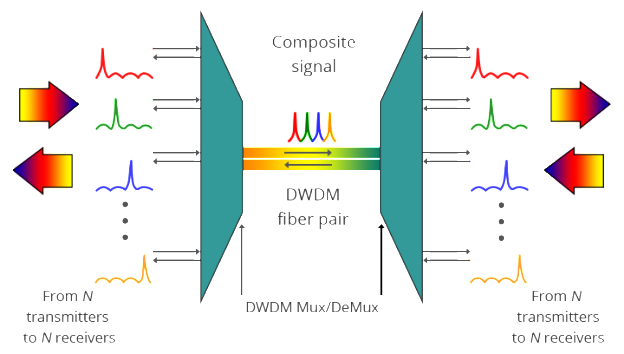
A typical DWDM system is composed of transmitter, receiver, optical amplifier, transponder, DWDM multiplexer and DWDM demultiplexer. They allow DWDM system to interface with other equipment and to implement optical solutions throughout the network, complying with the ITU channel standards.
- Optical transmitters/receiversTransmitters in DWDM systems provide the source signals which are then multiplexed. Multiple optical transmitters are used as the light sources in a DWDM system. We can also utilize a transceiver to replace transmitters and receivers to achieve the same purpose. Usually a DWDM transceiver applied in DWDM network can reach a transmission distance of up to 120km.
- Optical amplifiersOptical amplifiers (OAs) boost the amplitude or add gain to optical signals passing on a fiber by directly stimulating the photons of the signal with extra energy. They are "in-fiber†devices. OAs amplify optical signals across a broad range of wavelengths. This is very important for DWDM system application. Erbium-doped fiber amplifiers (EDFAs) are the most commonly used type of in-fiber optical fibre.
- TranspondersTransponders are designed to convert optical signals from one incoming wavelength to another outgoing wavelength suitable for DWDM applications. Transponders are optical-electricaloptical (O-E-O) wavelength converters. Within a DWDM system, a transponder converts the client optical signal back to an electrical signal (O-E) and then performs either 2R (reamplify, reshape) or 3R (reamplify, reshape, and retime) functions.A transponder is located between a client device and a DWDM system. From left to right, the transponder receives an optical bit stream operating at one particular wavelength (1310 nm). The transponder converts the operating wavelength of the incoming bitstream to an ITU-compliant wavelength. It transmits its output into a DWDM system. On the receive side (right to left), the process is reversed. The transponder receives an ITU-compliant bit stream and converts the signals back to the wavelength used by the client device.
- DWDM Multiplexers and DemultiplexersMultiple wavelengths (all within the 1550 nm band) created by multiple transmitters and operating on different fibers are combined onto one fiber by way of an optical multiplexer. The output signal of an optical multiplexer is referred to as a composite signal. At the receiving end, a demultiplexer separates all of the individual wavelengths of the composite signal out to individual fibers. The DWDM demultiplexers are capable of distinguishing each wavelength without crosstalk. The individual fibers pass the demultiplexed wavelengths to as many optical receivers. Typically, mux and demux (transmit and receive) components are contained in a single enclosure. Optical mux/demux devices can be passive. Component signals are multiplexed and demultiplexed optically, not electronically, therefore no external power source is required.

As occurs with many new technologies, the potential ways in which DWDM can be used are only beginning to be explored. Already, however, the technology has proven to be particularly well suited for several vital applications.
DWDM is ready made for long-distance telecommunications operators that use either point–to–point or ring topologies. The sudden availability of 16 new transmission channels where there used to be one dramatically improves an operator’s ability to expand capacity and simultaneously set aside backup bandwidth without installing new fiber.
This large amount of capacity is critical to the development of self-healing rings, which characterize today’s most sophisticated telecom networks. By deploying DWDM terminals, an operator can construct a 100% protected, 40 Gb/s ring, with 16 separate communication signals using only two fibers.
DWDM is the clear winner in the backbone. It was first deployed on long-haul routes in a time of fiber scarcity. Then the equipment savings made it the solution of choice for new long-haul routes, even when ample fiber was available. While DWDM can relieve fiber exhaust in the metropolitan area, its value in this market extends beyond this single advantage. Alternatives for capacity enhancement exist, such as pulling new cable and SONET overlays, but DWDM can do more. What delivers additional value is DWDM’s fast and flexible provisioning of protocol- and bit rate-transparent, data-centric, protected services, along with the ability to offer new and higher-speed services at less cost.
Posted by: jowang at
04:28 AM
| No Comments
| Add Comment
Post contains 788 words, total size 7 kb.
November 09, 2016
As new network architectures continue to demand ever higher speed, 40Gbps and 100Gbps Ethernet links are rapidly coming on line. In fact, volume is starting to build and switch port as well as transceiver prices are dropping rapidly. There are many new form factors for optical transceivers supporting a variety of transmission distances and fiber types. But they are not the prior focus of this post. Today, we’ll mainly bring two major trends to you. One major trend is the use of multiple parallel optical paths to achieve the total 40Gbps or 100Gbps interface transfer rate. The other is using multiple wavelengths and integrated wavelength division multiplexing to achieve multiple paths on single fibers.
Concerning modal dispersion when the speed is at or above 25Gbps, it is very challenging to achieve distance of more than 5 or 10 meters on multimode fibers. Therefore, most multimode transceiver implementations at 40G/100G use multiple parallel links each running at rates of 10Gbps or 25Gbps. While some may be familiar with the use of multi-fiber ribbon cables terminated with MPO connectors for interconnection between with fiber patch panels, these cables are now being used directly on 40G and 100G transceivers. Another result of moving more to parallel paths is expanded use of Direct Attached Cables (DACs, both fiber and copper). While DACs were somewhat popular as a low-cost alternative to fiber transceivers at 10Gbps, there increased bulk was a significant concern in some applications, like high density data centers. With the advent of ribbon fiber with MPO connectors on 40G/100G optical transceivers, the ‘bulk’ difference between copper and fiber connections is substantially lessened.
Since 40/100G Ethernet multimode QSFP modules use parallel optics technology which requires data transmission across multiple fibers simultaneously, multi-fiber connectors are needed. MPO (often referred to as MTP which is actually a brand name from US Conec) is the specified connector type for multi-mode 40/100G Ethernet. The fiber cable used with these connectors is typically OM3 although singlemode (OS1) is also in what are referred to as PSM (Parallel Single Mode) interfaces. Of course these connectors and cables are backward is compatible with legacy 1Gbps and 10Gbps interfaces.
The MPO connector is quite robust and features a keying mechanism so the connector only mates in on position. A common problem with previous duplex connectors (like dual-LC or dual-SC) is reversing of transmit and receive. Since the MPO connector contains both transmit and receive fibers and can only be assembled in a single orientation, this problem should be eliminated. A nice feature of the MPO connector is the audible locking "click†which occurs when the connector is seated. Also, the connector retention mechanism is very reliable. Once seated the connector cannot be separated without firmly grasping and pulling back on the plastic sleeve.
QSFP-40G-SR4 Ethernet uses a 12 position MTP/MPO connector interface. In the 12-fiber MTP/MPO connector, all these fibers are in a single row. The four leftmost fibers are used for transmit data, the middle four fibers are left unused, and the four rightmost fibers are used for receive data.
Three options are defined for the 100GBASE-SR10 Ethernet interface. This first two, shown below, use two separate 12 position MTP/MPO connectors, one for all of the Tx fibers and the other for the Rx fibers. Neither of these options appear to be actually used in commercial implementations. The 3rd option utilizing a 24 position MPO has become the de facto standard in the marketplace. The MPO is arranged in two rows of 12. The middle 10 fibers of each row are used while the outermost fibers at each end of the rows are vacant. 10 fibers in the upper row for transmitting data and the remaining 10 fibers in the lower row for receiving data.
Direct Attached Cables (DACs) are assemblies composed of a fixed length of copper or fiber cable with standard pluggable transceiver modules permanently fixed to each of its ends. There are many variations of DACs for a variety of 40G and 100G applications, among which 100G QSFP28 to 10X 10G SFP+ breakout cables and a 100G QSFP28 to 4X 25G QSFP are the most common variations.
The primary advantage of using DACs versus paired transceivers with a length of cable is cost savings. The biggest disadvantage is the fixed length of the assemblies. In applications where location of equipment is carefully planned in advance and link lengths are known quite accurately and will remain fixed over the life of the installation where DACs can be a very economical alternative.
As IT infrastructures migrate to 40G and 100G speeds, network designers must carefully weigh alternative implementations of such links. DACs are a low cost alternative to more flexible pluggable transceivers interconnected by fiber. New MPO connectors with their multi-fiber ribbon cables may be new an unfamiliar versus the ubiquitous SC and LC fiber connectors of the past. However, by understanding the keying and pinout arrangements of MPO connections, reasonable multimode and low cost singlemode connections are possible even at 40G and 100G speeds.
Posted by: jowang at
02:20 AM
| Comments (3)
| Add Comment
Post contains 849 words, total size 6 kb.
As new network architectures continue to demand ever higher speed, 40Gbps and 100Gbps Ethernet links are rapidly coming on line. In fact, volume is starting to build and switch port as well as transceiver prices are dropping rapidly. There are many new form factors for optical transceivers supporting a variety of transmission distances and fiber types. But they are not the prior focus of this post. Today, we’ll mainly bring two major trends to you. One major trend is the use of multiple parallel optical paths to achieve the total 40Gbps or 100Gbps interface transfer rate. The other is using multiple wavelengths and integrated wavelength division multiplexing to achieve multiple paths on single fibers.
Concerning modal dispersion when the speed is at or above 25Gbps, it is very challenging to achieve distance of more than 5 or 10 meters on multimode fibers. Therefore, most multimode transceiver implementations at 40G/100G use multiple parallel links each running at rates of 10Gbps or 25Gbps. While some may be familiar with the use of multi-fiber ribbon cables terminated with MPO connectors for interconnection between with fiber patch panels, these cables are now being used directly on 40G and 100G transceivers. Another result of moving more to parallel paths is expanded use of Direct Attached Cables (DACs, both fiber and copper). While DACs were somewhat popular as a low-cost alternative to fiber transceivers at 10Gbps, there increased bulk was a significant concern in some applications, like high density data centers. With the advent of ribbon fiber with MPO connectors on 40G/100G optical transceivers, the ‘bulk’ difference between copper and fiber connections is substantially lessened.
Since 40/100G Ethernet multimode QSFP modules use parallel optics technology which requires data transmission across multiple fibers simultaneously, multi-fiber connectors are needed. MPO (often referred to as MTP which is actually a brand name from US Conec) is the specified connector type for multi-mode 40/100G Ethernet. The fiber cable used with these connectors is typically OM3 although singlemode (OS1) is also in what are referred to as PSM (Parallel Single Mode) interfaces. Of course these connectors and cables are backward is compatible with legacy 1Gbps and 10Gbps interfaces.
The MPO connector is quite robust and features a keying mechanism so the connector only mates in on position. A common problem with previous duplex connectors (like dual-LC or dual-SC) is reversing of transmit and receive. Since the MPO connector contains both transmit and receive fibers and can only be assembled in a single orientation, this problem should be eliminated. A nice feature of the MPO connector is the audible locking "click†which occurs when the connector is seated. Also, the connector retention mechanism is very reliable. Once seated the connector cannot be separated without firmly grasping and pulling back on the plastic sleeve.
QSFP-40G-SR4 Ethernet uses a 12 position MTP/MPO connector interface. In the 12-fiber MTP/MPO connector, all these fibers are in a single row. The four leftmost fibers are used for transmit data, the middle four fibers are left unused, and the four rightmost fibers are used for receive data.
Three options are defined for the 100GBASE-SR10 Ethernet interface. This first two, shown below, use two separate 12 position MTP/MPO connectors, one for all of the Tx fibers and the other for the Rx fibers. Neither of these options appear to be actually used in commercial implementations. The 3rd option utilizing a 24 position MPO has become the de facto standard in the marketplace. The MPO is arranged in two rows of 12. The middle 10 fibers of each row are used while the outermost fibers at each end of the rows are vacant. 10 fibers in the upper row for transmitting data and the remaining 10 fibers in the lower row for receiving data.
Direct Attached Cables (DACs) are assemblies composed of a fixed length of copper or fiber cable with standard pluggable transceiver modules permanently fixed to each of its ends. There are many variations of DACs for a variety of 40G and 100G applications, among which 100G QSFP28 to 10X 10G SFP+ breakout cables and a 100G QSFP28 to 4X 25G QSFP are the most common variations.
The primary advantage of using DACs versus paired transceivers with a length of cable is cost savings. The biggest disadvantage is the fixed length of the assemblies. In applications where location of equipment is carefully planned in advance and link lengths are known quite accurately and will remain fixed over the life of the installation where DACs can be a very economical alternative.
As IT infrastructures migrate to 40G and 100G speeds, network designers must carefully weigh alternative implementations of such links. DACs are a low cost alternative to more flexible pluggable transceivers interconnected by fiber. New MPO connectors with their multi-fiber ribbon cables may be new an unfamiliar versus the ubiquitous SC and LC fiber connectors of the past. However, by understanding the keying and pinout arrangements of MPO connections, reasonable multimode and low cost singlemode connections are possible even at 40G and 100G speeds.
Posted by: jowang at
02:20 AM
| No Comments
| Add Comment
Post contains 849 words, total size 6 kb.
October 27, 2016
With the increasing demands for service needs and layered bandwidth management, the main challenge for service providers is to provide more and cheaper bandwidth and integrated services using different methods. This post will introduce a method that upgrades your network to 500G with DWDM (dense wavelength division multiplexing) technology.
As we have known, network operators are facing the pressure to increase bandwidth in an economical way. In order to release this pressure, there are three available methods to solve this problem. The first one is to lay more fibers directly. Second one is to increase the bit rate using TDM (time division multiplexing). The last to deploy DWDM technology. However, compared with the last one, the former two ways are either too costly or will cause other problems. While using DWDM technology, several wavelengths, or light colors, can simultaneously multiplex signals of 2.5 to 40 Gbps each over a strand of fiber. Without having to lay new fiber, the effective capacity of existing fiber plant can routinely be increased by a factor of 16 or 32. DWDM MUX/DEMUX systems with 40 and 96 wavelengths are in operation today, with higher density on the horizon.
In a DWDM system, each lambda can carry its own independent signal, providing the same overall bandwidth per channel (approximately 2.4 Gbps with most of today's fiber) that a single-color laser does. Thus, if you run DWDM with eight lambdas (eight channels), you increase the capacity of a fiber pair from 2.4 Gbps to 19.2 Gbps. This creates virtual dark fiber, which enterprise networks can use to run multiple higher-layer technologies such as ATM and Gigabit Ethernet simultaneously over the same physicalfiber strands.

Generally speaking, we use DWDM SFP+ transceivers with DWDM Mux/Demux system to expand our network. Under this condition, each wavelength can be transmitted at 10 Gbps. Therefore, if we deploy a 40 channels DWDMMux/Demux system, we can achieve 400G over a fiber pair. Then, How about another 100G? Actually, there is a 1310nm port integrated in a 40 channels DWDM Mux/Demux system. The 1310nm added port is a Wide Band Optic (WBO) port added to other specific DWDM wavelengths in a module. When we run out of all channels in a DWDM Mux/Demux system, we can add extra optics via this 1310nm port.
You should note that the optical components you added must be working in 1310nm. For example, 40G LR4 1310nm QSFP transceivers, 40G ER4 1310nm QSFP transceivers and 100G LR4 1310nm CFP2 transceivers etc. In above solution, we only need to plug 100G LR4 1310nm CFP2 fiber optic transceiver into the terminal equipment (Ethernet switch, router etc.) , then use the patch cable to connect it to your existing DWDM network via a 1310nm band pass port on the DWDM multiplexer. Then this set-up allows the transport of up to 40 x10Gbps plus 100Gbps over one fiber pair, in total 500Gbps! Similarly, if you use the 40G LR4 1310nm QSFP transceivers, you can then achieve 40 x10Gbps plus 40Gbps over one fiber pair, in total 440Gbps.

By using DWDM technology, requirements for extended distance can be solved. And service providers also can expand capacity in any portion of their networks flexibly, which any other technology cannot offer. Apart from the products mentioned above, FS.COM also offers other WDM/CWDM/DWDM products to meet your network infrastructure requirements.
Posted by: jowang at
09:22 AM
| Comments (1)
| Add Comment
Post contains 583 words, total size 5 kb.
September 29, 2016
Quad small form-factor pluggable plus (QSFP+) direct attach copper (DAC) cables are cables with QSFP+ module at one end or both ends. They are suitable for in-rack connections between QSFP+ ports of EX Series switches. They are suitable for short distances of up to 10 meters, making them ideal for highly cost-effective networking connectivity within a rack and between adjacent racks. This article will introduce EX Series switches and QSFP+ DAC for EX Series switches.
EX Series switches deliver scalable port densities and carrier-proven high availability features that consolidate legacy switch layers, helping to reduce capital and operational expenses and advance the economics of networking. For example, the EX 4200 series Ethernet switches with Virtual-Chassis technology, deliver the same Gigabit Ethernet (GbE) and 10GbE port densities as traditional chassis-based switches, but at one-eighth the footprint and less than one third the cost. The EX Series switches are right-sized for campus, data center and remote office environments and feature many of the same carrier-class hardware and software architectures found in core routers that were purpose-built to support the convergence of data, voice, and video onto a single always-on network.

By alleviating the cost, complexity and risk associated with legacy switch infrastructures, the EX Series switches enable high-performance businesses to deploy a high-performance network infrastructure based on three key tenets – operational simplicity, carrier-class reliability, and integration and consolidation – to enable ubiquitous access to strategic assets, reduce network downtime and enhance overall security to shared assets across the extended enterprise.
QSFP+ direct attach copper (DAC) cable is hot-removable and hot-insertable. QSFP+ DAC mainly has two kinds. One is a cable that connects directly into two QSFP+ modules, one at each end of the cable. The cables use integrated duplex serial data links for bidirectional communication and are designed for data rates up to 40 Gbps. The other is a breakout cable consisting of a QSFP+ transceiver on one end and four SFP+ transceivers on the other end. The QSFP+ transceiver connects directly into the QSFP+ access port on the QFX Series device. The cables use high-performance integrated duplex serial data links for bidirectional communication on four links simultaneously. The SFP+ links are designed for data rates up to 10 Gbps each.
The following table describes the software support for QSFP+ passive DAC cable lengths on EX Series switches for Junos OS releases.
|
Switch |
Software Support Added |
DAC Model Number |
|---|---|---|
|
EX44300 switches |
Junos OS for EX Series switches, Release 13.2X51-D15 or later |
|
|
EX4300 switches |
|
|
|
EX4550 switches |
|
|
QSFP+ direct attach copper cables can provide cost-effective and reliable 40G speed connections for EX Series switches with distances reaching up to 10 meters. As the leading fiber optical manufacturer in China, FS.COM offers various types of QSFP+ DAC with low cost but high performance. Apart from the above-mentioned, FS.COM offers Cisco QSFP+ breakout cable as well. All these DACs are with 100% compatibility and can be customized according to your particular needs.
Posted by: jowang at
03:50 AM
| No Comments
| Add Comment
Post contains 590 words, total size 8 kb.
September 13, 2016
Gigabit Ethernet technology is an extension of the 10/100-Mbps Ethernet standard, providing a raw data bandwidth of 1000 Mbps while maintaining full compatibility with the installed base of over 70 million Ethernet nodes. A Gigabit Ethernet is imperative for two reasons: faster systems and faster backbones. Gigabit Ethernet has the potential for low-cost products, freedom of choice in selecting the products, interoperability, and backward compatibility. Gigabit Ethernet supports existing applications, network operating systems, and network management; it requires a minimal learning curve for Ethernet network administrators and users. These investment preservation and risk minimization aspects are what make Gigabit Ethernet so attractive. With the development of Ethernet systems and the growing capacity of modern silicon technology, embedded communication networks are playing an increasingly important role in embedded and safety critical systems.

A known type of data communication device is a small form factor pluggable (SFP) module. Typically, the SFP module plugs into an interface slot in a circuit board populated with other communication devices used in an Ethernet-based system. The SFP module includes a second serial interface, interconnected with the circuit board slot, and a first serial interface, coupled to a serial link, such as a copper or fiber link, for communicating with remote link partners. The serial link, coupled with the first serial interface, may be a 10/100/1000 Base-T copper link, or a fiber link, for example. The SFP module also offers several significant advantages over its predecessor, the GBIC (Gigabit Interface Converter), including lower cost, lower power, and smaller size. Thus, with the SFP form factor, fiber Gigabit systems may be developed featuring similar port densities as copper-only systems using RJ-45 connectors.
The SFP transceiver Multi-source Agreements (MSA) document puts forward a specification for the development of optical SFP modules based on IEEE 802.3z, the Gigabit Ethernet Standard. Specifically, the MSA calls out 1000Base-X Physical Coding Sub-layer (PCS) which supports full-duplex binary transmission at 1.25 Gbps over two copper wire-pair SerDes (Serializer/Deserializer). Transmission coding is based on the ANSI Fiber Channel 8B/10B encoding scheme.
1000Base-X makes no provision for running at slower speeds. Thus, network device ports utilizing SFPs are dedicated to operating on fiber links at speeds of 1000 Mbps. However, more than 85% of office space inside buildings is category 5 copper. Thus, ports designed to use optical SFPs can not make use of this existing cabling.
For example, a customer may require a network device, such as a router, having both optical ports for long distance connections and RJ-45 copper ports for connecting to local devices. It is often the case that not all optical ports provided on a router are needed at a given time. However, with conventional SFPs these optical ports cannot be utilized to connect with local devices connected by standard copper cabling or operating at speeds lower than 1000 Mbps. But with a 1000BASE-T copper SFP transceiver, the customer could use their existing copper cabling infrastructure instead of replacing the infrastructure. Here are two good examples of 1000BASE-T SFP transceivers, the Finisar FCLF-8521-3 compatible 1000BASE-T SFP copper transceiver and Cisco Linksys MGBT1 compatible 1000BASE-T SFP copper transceiver from FS.COM. Both of them are designed for 100m reach over Cat 5 UTP cable with RJ-45 interface and support max data rate of 1000Mbps.
The 1000BASE-T copper SFP transceiver offers a flexible and simple method to be installed into SFP MSA compliant ports at any time with no interruption of the host equipment operation. It enables for seamless integration of fiber with copper LAN connections wherever SFP interface slots can be found. Such system is economical, it saves time, offers flexibility and eliminates the necessity for replacing entire devices once the customers have to change or upgrade fiber connections and you will benefit so much from it.
Posted by: jowang at
04:28 AM
| Comments (4)
| Add Comment
Post contains 630 words, total size 5 kb.
42 queries taking 0.0581 seconds, 126 records returned.
Powered by Minx 1.1.6c-pink.

