


December 22, 2016
The last few decades have seen the broad adoption of fiber optic transceivers used in optical communications for both telecommunication and data communications applications. However, would the copper connectivity withdraw from the market? Copper medium usually doesn’t require any transceivers, as they are part of the interface module. However, in order to cut down expenditures, some vendors use SFP copper transceiver with an RJ-45 female connector for Gigabit Ethernet connectivity over copper medium, or XFP copper transceiver for 10Gigabit Ethernet (10GbE) connectivity over CX4 copper. This article will give you a complete guide to these copper transceivers.
Supporting 10/100/1000 Mbps data-rate in excess of 100 meters (325 feet) reach over UTP Category5/5e cables, copper transceiver module is ideally suited for implementing small form-factor Network Interface Cards (NICs) and uplinks. As such, it is highly appropriate for use in high-density applications such as LAN 1000BASE-T, switch-to-switch interfaces, switched backplanes, blade servers, gaming devices, and router/server interfaces.
With the development of 1000BASE-T technology, 1000BASE-T and 100BASE-TX copper SFP transceiver over Category 5 copper cabling is an attractive option for network. The advantages are listed as follows:
- For 100m reach over Cat 5 UTP cable
- Hot-pluggable SFP footprint
- Supports RX_LOS as link indication function
- Fully metallic enclosure for low EMI
- Low power dissipation (1.05 W typical)
- Compact RJ-45 connector assembly
- Compliant with SFP MSA and IEEE Std 802.3-2002
As a kind of copper XFP transceiver, the XFP 10GBASE-CX4 module uses a CX4 connector to provide a connection to up to 15 meters over CX4 grade copper cable. Transparently to the user, the module transfers the 10GbE data stream over four full-duplex 3.125 Gbps channels over a single parallel copper cable. The product offers the ability to scale bandwidth in 10G increments, and directly with the industry standard MDI electrical socket.
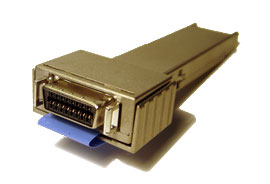
CX4 is an extension of the four-channel 10 Gbps XAUI interface and is available in 70-pin MSA transponder modules, otherwise known as Xenpak, XPAK and X2. The 10GBASE-CX4 solution employs an Infiniband-style Twin-AX cable (click to see the Cisco 10G twinax). In this case, eight 100-ohm differential Twin-AX cables are bundled into a single outer shield. The center conductors are 24 AWG wire for compatibility with printed circuit board termination inside the connector housing. The limitation of the 10GBASE-CX4 solution is that it requires a 70-pin MSA socket and only supports the IEEE802.3ae 10GE data format.
The XFP format also offers the distinct feature of being data agnostic, which opens the market for the copper based solution to telecommunications applications as well. The 10 Gbps serial solution over copper adds the final link option to the XFP industry, offering everything from the ultra low-cost sub-20m 10 Gbps shelf-to-shelf and rack-to-rack links to 80 km or longer optical links.
Among the above-mentioned copper transceivers, what must be noticed is that copper SFP transceiver offers a flexible and simple method to be installed into SFP MSA compliant ports at any time with no interruption of the host equipment operation. It enables for seamless integration of fiber with copper LAN connections wherever SFP interface slots can be found. Such system is economical, it saves time, offers flexibility and eliminates the necessity for replacing entire devices once the customers have to change or upgrade fiber connections and you will benefit so much from it.
Posted by: jowang at
03:18 AM
| Comments (1)
| Add Comment
Post contains 551 words, total size 4 kb.
December 15, 2016
Customers for fiber optic cable installations usually require documentation of test results before accepting and paying for the work. Testing needs to be done carefully to ensure the measurements are accurate and reliable. A definitive repertoire of tests, known as the "essential six," can benefit the inexperienced system engineer. Six basic test procedures measure distance, fiber loss, event loss, link loss, event-return loss and link-return loss. These procedures are implemented at all four levels of fiber operation, including pre-installation, installation and acceptance, maintenance and restoration.
An OTDR can be used to accomplish the six test procedures. In addition, clean connections on the fiber media under test are imperative. All six test procedures will prove inaccurate or impossible to accomplish if the fiber-optic connectors are dirty.
The optical distance between one point and another depends on definition. For example, the distance could be the fiber-cable length between a transmitter and a receiver, or it could be the fiber-cable length between two splices. An OTDR is the test instrument used worldwide to measure optical test events either automatically or manually. Events are detected as disturbances in the OTDR's relatively linear trace display.

To measure optical distance between two points, the OTDR launches a laser-generated light pulse down the fiber at the transmission end of the cable. The instrument then detects the backscatter returned from the fiber and any reflections from shiny surfaces. It measures the time taken by the light pulse to make the round trip on the fiber and calculates that time into distance.
One minor deviation in this test is the difference between real and apparent distance. The optical, or apparent distance, is the distance reading registered on the OTDR, and is always longer than the real distance. One reason for the distance difference results from the undulation of fiber as it resides within loose-tube cable, which adds to its length. Another reason involves buried cable as it winds within a trench, thereby producing a longer optical length.
The backscatter trace is a representation of the fiber itself. The slope of the backscatter trace discloses that less and less light is being reflected back as the length of the fiber increases. This slope represents fiber loss, a manufacturer's specification. Typical fiber-loss measurements are given as the amount of light (in decibels) lost per kilometer. For example, a long-haul telephone fiber might lose 0.15 dB/km, whereas a multimode local area network fiber could lose 3 dB/km. Fiber loss is always measured along a featureless section of backscatter with no events to skew the calculation.
A test event is a disturbance that occurs above or below the backscatter baseline. Splices, connectors, bends and cracks are typical events that produce trace disturbances on the OTDR display. Normally (but not always), an event results in a loss of light. There are two types of events--reflective and non-reflective. The spikes along the baseline indicate a reflection. Because more photons appear and thus exceed the normal backscatter level, a mechanical splice or the end of the fiber is revealed. Other causes of reflections are connectors and fiber cracks.
Events that occur along the fiber become important when a fiber-loss budget is calculated. Only a finite amount of light is launched by the transmitter. Consequently, if the receiver does not receive enough light, a major cable problem has occurred.
Link loss is the total amount of light lost between two points. A link can be the distance between events or between two end points. Total link loss is typically specified when it directly affects the loss budget. If the link loss is a high value, then specific events are consuming light.
Return loss is essentially the light lost because of reflections back toward the transmission or source end. The shiny surfaces of connectors and mechanical splices reflect light. Some of this reflected light returns to the source. Any transmitted light that does not reach the end of the fiber is lost. An OTDR trace displays return loss as the height of a reflection.
Return loss is defined as the ratio in dB of the incident power to the reflected power. Return loss is always expressed as a positive number:
In contrast, reflectance is defined as the ratio of reflected power to the incident power or the inverse of the return-loss formula. When expressed in decibels, reflectance is a negative number. In addition, reflectance can be expressed in terms of density or as a percentage.
In reality, these terms mean noise. The reflected light travels back to the source, reflects off the input and makes another round trip. To a digital system, the reflected light looks like a bit error. To an analog system, such as cable TV, reflected light creates sparkle. The higher the reflection value, the more dramatic the noise level becomes.
Link-return loss is similar to link loss. It is the total amount of reflected light in the link. Therefore, link-return loss is often used as an acceptance test. If the total amount of return loss is below a certain level, the link is assumed not to contain a single event reflecting above specification.
These six essential tests should be used to test fiber during pre-installation, installation and acceptance, and for maintenance andrestoration. A pre-installation test should be performed when fiber-optic cable arrives from the vendor. This receiving type of test is important because it quickly and easily determines product acceptance or rejection before system usage.
Posted by: jowang at
03:52 AM
| No Comments
| Add Comment
Post contains 925 words, total size 7 kb.
December 06, 2016
Over the years of SFP transceiver communication existence, there have been numerous different standards introduced. The great thing about SFP transceivers in networking hardware is that they allow a single piece of equipment, such as a switch, to support different wiring and transmission formats. The problem comes when trying to figure out which of the many transceiver types out there you need. There are several different types of SFP transceivers capable of supporting a multitude of communication standards, such as: CWDM/DWDM, SONET, Fibre Channel, Fast Ethernet and Gigabit Ethernet.

WDM, or wavelength-division multiplexing, is a type of technology that allows a transceiver to have different wavelengths assigned to it.Coarse wavelength-division multiplexing (CWDM) SFP transceivers are capable of transmitting data at eight different wavelengths ranging from 1470nm to 1610nm. CDWM SFP transceivers are color coded, to help identify which wavelength is mapped to the transceiver.Dense wavelength-division multiplexing (DWDM) SFP transceivers are available in 32 different wavelengths, and offer high-capacity bandwidth for serial optical data communications. DWDM SFP transceivers are slightly more expensive than CWDM SFP transceivers, but the more densely spaced channels allow for a greater number of wavelengths to travel over a single fiber.Both CWDM and DWDM SFP transceivers can be used to transmit data over Gigabit Ethernet, SONET and Fibre Channel.
Synchronous optical networking (SONET) technology enables the transmission of a large volume of data over long distances. SONET can be used to transmit multiple streams of data simultaneously over fiber optic mediums using laser beams and LEDs.SFP transceivers are built to transmit data over SONET at varying rates (OC-3, OC-12 and OC-4![]() and with different reaches (short-reach, intermediate-reach, and long-reach). SONET SFP transceivers are able to transmit data over both singlemode and multimode fiber.
and with different reaches (short-reach, intermediate-reach, and long-reach). SONET SFP transceivers are able to transmit data over both singlemode and multimode fiber.
Fibre Channel is a protocol which is used primarily in "Storage Area Networks". It comes in different speeds like 1xFC, 2xFC, 4xFC, 8xFC and 16xFC. Fibre Channel was developed as a lossless protocol in a time when switches were less reliable than they are today. When using Ethernet as a protocol, frames were dropped, which created a problem for applications like data traffic. With the advent of greater technology, switches are now much more reliable; however, Fibre Channel still holds a small advantage over Ethernet when it comes to consistency and latency.Fibre Channel SFP transceivers are modules commonly used in storage area networks (SAN) and are available in 1, 2, 4, 8, 10, 16 and 20Gbps data transmission rates. Fibre Channel SFP transceivers can be used in both singlemode and multimode fiber applications.
Fast Ethernet is slowly being replaced with Gigabit Ethernet. Fast Ethernet SFP transceivers were originally designed to transmit data at 10Mbps, and eventually reached transmission speeds of 100Mbps (100Base). 100Base rate Fast Ethernet transceivers are available in the following interface types: FX, SX, BX and LX10.With the development of Gigabit Ethernet, SFP transceiver transmission rates increased to 1000Mbps (1000Base). 1000Base rate Gigabit Ethernet SFP transceivers are available in the following interface types: T, SX, LX, LX10, BX10, and the non-standard EX and ZX.
FS.COM is sure to have the right SFP transceiver for your network! We carry a full line of both name-brand and affordable 100% compatible transceivers of every type your business could possibly need. Contact us today for a free consultation on which standards meet your business needs, or to discuss fiber connectivity network solutions that will best support your future business plans.
Posted by: jowang at
08:47 AM
| Comments (1)
| Add Comment
Post contains 585 words, total size 5 kb.
35 queries taking 0.0751 seconds, 73 records returned.
Powered by Minx 1.1.6c-pink.

