


December 30, 2015
SFP+ and XFP are two terms for a type of transceiver that is plugged into a special port on a switch or other network device to convert the port to a copper or fiber interface. They are used in the field of telecommunication and data communication. Generally speaking, both of them are 10G fiber optical modules and can connect with other type of 10G modules. What's the difference between SFP+ and XFP? And what's the connection?
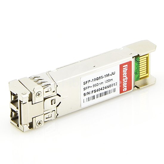
SFP+, the enhanced small form-factor pluggable, is an enhanced version of the SFP that supports data rates up to 16Gbit/s. SFP+ is a hot-swappable and protocol-independent module. SFP+ supports 8Gbit/s Fibre Channel, 10 Gigabit Ethernet and Optical Transport Network (OTN) standard OTU2. It is a popular industry format supported by many network component vendors. Although the SFP+ standard does not include mention of 16G Fibre Channel it can be used at this speed. Consideration has to be given to whether the module is linear or limiting. Linear SFP+ modules are most appropriate for 10GBASE-LRM; otherwise, limiting modules are preferred. SFP+ also introduces direct attach for connecting two SFP+ ports without dedicated transceivers. The image below shows a Juniper EX-SFP-10GE-USR 10GbE SFP+ transceiver.
XFP, 10 Gigabit small form factor pluggable, is a standard for transceivers for high-speed computer network and telecommunication links that use optical fiber. It was defined by an industry group in 2002, along with its interface to other electrical components, which is called XFI. XFP is also a hot-swappable and protocol-independent module. It typically operates at near-infrared wavelengths (colors) of 850nm, 1310nm or 1550nm. And it can operate over a single wavelength or use dense wavelength-division multiplexing techniques. XFP modules use an LC fiber connector type to achieve higher density. Principal applications include 10 Gigabit Ethernet, 10Gbit/s Fibre Channel, synchronous optical networking (SONET) at OC-192 rates, synchronous optical networking STM-64, 10Gbit/s OTN OTU2, and parallel optics links. With XFP you will surely experience a fast transmission of data in your computer network including your telecommunication links. The image below shows a Cisco XFP-10GER-192IR+ 10GBASE-ER XFP transceiver.

- 1.The size of SFP+ is smaller than XFP. The smaller SFP+ transfer the modulation functions, serial/deserializer, MAC, clock and data recovery (CDR) and EDC functions from the module to the motherboard on the card. SFP+ modules leave more circuitry to be implemented on the host board instead of inside the module.
- 2.XFP is based on the standard of XFP MSA; SFP+ is compliant with the protocol of IEEE802.3ae, SFF-8431, SFF-8432.
- 3.SFP+ is a more compact factor package than compared to that of XFP.
- 4.The cost of SFP+ is less than that to the XFP.
- 1.Both of them are 10G fiber optical modules, share the same features with other 10G transceivers and can connect with other type of 10G modules.
- 2.SFP+ now has replaced the XFP and becomes the main stream of 10G transceivers markets.
- 3.SFP+ and XFP are compact transceivers which function as modular connectors.
- 4.Available for copper (RJ-45) and for all common fiber modes, wavelengths and data rates, SFP+ and XFP allow network operators to connect different interface types to the same network equipment, via an SFP+/XFP port.
The fiber optic transceivers, as the core of optoelectronic device in the WAN, MAN or LAN application, have also developed various types along with the increasing in complexity. The cost of cable upgrades is greatly reduced, preserving the investment in costly networking equipment, for the price of a relatively inexpensive SFP+ or XFP. More and more network equipment is being designed with SFP+/XFP ports, to take advantage of this flexibility, and to take the uncertainty and guesswork out of expensive equipment purchases.
Posted by: jowang at
06:31 AM
| No Comments
| Add Comment
Post contains 623 words, total size 7 kb.
December 28, 2015
Polarization maintaining (PM) fiber optic patch cord is a kind of special fiber optic patch cord. It can be used in many areas. Here's what you need to know about PM fiber patch cords if your designs require them.
PM fiber patch cord is a fiber optic cable made with PM fiber and terminated on both ends with high-quality ceramic fiber connectors. A PM optical fiber is a single mode optical fiber in which linearly polarized light, if properly launched into the fiber, maintains a linear polarization during propagation, exiting the fiber in a specific linear polarization state. If the polarization of the input light is not aligned with the stress direction in the fiber, the output light will vary between linear and circular polarization (and generally will be elliptically polarized). And the exact polarization will also be sensitive to variations in temperature and stress in the fiber. The light shall be coupled at the fiber entrance parallel to the slow axis or to the fast axis, then the maintaining of the polarization is therefore possible. PM fiber patch cord is a base device of optical passive component. It also features low insertion loss, high extinction ratio, high return loss, excellent changeability over a wide wavelength range and excellent environmental stability and reliability. The following picture shows PM fiber patch cords.

There are a wide variety of PM fiber patch cords available that support different data rates and suit various connector types. According to different criteria, PM fiber patch cords can be categorized into various types. The following is some detailed information about types of PM fiber patch cords based on 4 different criteria:
Classification by connector type―PM fiber patch cords are capped at both ends with fiber connectors. FC, SC, LC and ST are the commonly used connector types for PM fiber termination. According to the connectors on the both ends, there are many different kinds of PM fiber patch cords, such as LC-FC, SC-FC, or FC-FC PM fiber patch cords.
Classification by fiber type―PM fiber patch cords are built with polarization maintaining fiber. To ensure the polarization of both the input and output light in a PM fiber, several different shapes of rod are used, and the resulting fiber is sold under brand names such as "Panda" and "Bow-tie". With different PM fiber, there are corresponding PM fiber patch cords, such as Panda PM fiber patch cords and Bow-tie PM fiber patch cords.

Classification by cable type―PM fiber patch cords can also be categorized according to the cable types. There are mainly three kinds of cable types, 250um bare fiber, 900um loose tube jacket and 3mm loose tube jacket. So based on the cable types, there are 3 kinds of PM fiber patch cords.
Classification by fiber length―The standard length is 1 meter. It can vary for special requirements. The length of PM fiber patch cords can be custom made.
PM fiber patch cords are often used in polarization sensitive fiber optical systems for transmission of light that requires the PM state to be maintained. PM optical patch cord is a special optical component using the properties of optical fibers specially manufactured so that its transmission parameters can support a particular application. They have a large number of uses, including high-data-rate communications systems, polarization sensitive components, and interferometric sensors. They are also widely used in PM fiber amplifiers, fiber lasers, high speed communication systems, testing equipment and instrumentation applications. Area of use of PM fiber patch cords is very broad and includes equipment such as instrumentation, spectroscopy, aerospace, medical diagnostics and many other industrial applications.
Understanding polarization has become a necessity in today's fiber optic communication systems and applications. Knowing more about PM fiber patch cord can help you to choose. Fiberstore is a professional manufacturer and supplier, which offers a large amount of fiber optic patch cables. There are various fiber jumpers with different connector types for you to choose, like LC-LC fiber patch cord, SC fiber patch cable, and SC to LC patch cord. Our fiber optic patch cords are made and custom to order worldwide.
Posted by: jowang at
04:22 AM
| No Comments
| Add Comment
Post contains 706 words, total size 7 kb.
December 24, 2015
Written by Tim Skinner

TIM, the new name for Telecom Italia, has announced its launch of voice over LTE and LTE-A services across the county.
The operator has clarified that it is early days for the HD voice service, and said new functionality will be added in the not too distant future.
"The service will later be extended to other offerings in the portfolio… and will be enriched by new options such as high-definition video, the sharing of video, images and maps in real-time chat and file transfer," the telco said.
Aside from HD voice and lower levels of latency users experience when making a call, one of the other primary benefits of VoLTE is that it removes the need for 3G fallback when LTE users make a call. Traditionally, users will use 4G/LTE services, but the device will need to hop onto the 2G/3G network to make the call. As a consequence, 4G services aren’t useable for the duration of any calls being made. To that extent, TIM said its service "VOCE 4G" ("Voice 4G") will allow users to surf the internet and utilise their favourite apps without interrupting the call.
Meanwhile, the telco has also announced the launch of its LTE-A service, "4G Plus". By utilising Three Carrier Aggregation technology, TIM claims it can provide 300Mbps mobile download speeds across eight Italian cities to users.
Finally, to encourage users into using each new feature, TIM has dovetailed the two launches with an incentivised free gigabyte of 4G data over Christmas. "Natale Giga Gratis" will give users the free data just by downloading the TIM mobile app.
" 'VOICE 4G' and 'Christmas Giga free' enrich the offerings of Telecom Italy, united under the single TIM brand, in order to meet the needs of all customers and to new digital consumption," said the telco.
Tags: data, featured, LTE-A, TIM, VoLTE
Posted by: jowang at
04:20 AM
| No Comments
| Add Comment
Post contains 320 words, total size 3 kb.
December 22, 2015
The storage requirements of industry today has grown exponentially over the last decade. Not only has the volume of storage increased, but the added requirements for reliable, high-speed, highly-available storage have left the industry seeking for new solutions. There are a number of choices available each with its own advantages and disadvantages. This article offers an overview of one of the debated technology, Fibre Channel.
Fibre Channel, or FC, is a serial interconnection technology that was developed to bring together elements from the channel and networking technologies. It is standardized in the T11 Technical Committee of the International Committee for Information Technology Standards (INCITS). This union provides a reliable high-speed transport for data over long distances. Channel technology provides switched point-to-point connections between the communicating devices. This is usually a hardware centered approach with very high-speed, low-overhead communication. Fibre Channel combines the reliability and speed of the channel technologies with the distributed nature of the network technologies to create a new I/O interface meeting the needs of both environments. And now it has become a common connection type for storage area networks (SAN) in enterprise storage. Fibre Channel commonly runs at 2, 4, 8 and 16 gigabit per second rates. The following picture shows a Finisar FTLF8519P3BNL 2G Fibre Channel SFP transceiver on the left and a HP AJ716A 8G Fibre Channel SFP+ transceiver on the right.

For demanding applications, Fibre Channel technology has entrenched itself as the quintessential SAN interconnect, providing high speed, high reliability, and inherent security for storage network users. Fibre Channel uses optical fiber, coaxial copper or twisted pair copper cabling to carry SAN data at speeds of 1Gbps, 2Gbps, 4Gbps and 10Gbps. At the same time, latency is kept very low, minimizing the delay between data requests and deliveries. It is this combination of high speed and low latency that makes FC an ideal choice for time-sensitive or transactional processing environments. Fibre Channel is especially suited for connecting computer servers to shared storage devices and for interconnecting storage controllers and drives. Fibre Channel is three times as fast, it has begun to replace the Small Computer System Interface (SCSI) as the transmission interface between servers and clustered storage devices. Fibre Channel offers point-to-point, switched, and loop interfaces. It is designed to interoperate with SCSI, the Internet Protocol (IP) and other protocols.
Why choose Fibre Channel? Here are the reasons. Fibre Channel is regarded as a very reliable SAN technology. The FC SAN fabric allows for multiple connection paths and redundant connections, so if a hardware fault or cabling issue arises, a new path can be found and communication can fail over to an alternate connection—keeping storage and applications connected (even at reduced performance) until corrective action can be taken. Alternatively, multiple connections can be aggregated (or trunked) for even better bandwidth. The availability of multiple or redundant connections enables load balancing where SAN traffic is analyzed and can be dynamically rerouted from busy paths (bottlenecks) through less-used paths. Security is another important attribute of Fibre Channel technology. Zoning makes it possible for devices within a Fibre Channel network to see each other. By limiting the visibility of end devices, servers (hosts) can only see and access storage devices that are placed into the same zone. Once the SAN is zoned, LUNs (logic unit numbers) are masked so that each host server can only see specific LUNs. Moreover, Fibre channel is more flexible; devices can be as far as ten kilometers (about six miles) apart if optical fiber is used as the physical medium.
However, there are some recognized disadvantages to FC. Fibre Channel has been widely criticized for its expense and complexity. A specialized HBA (hose bus adapter) card is needed for each server. Each HBA must then connect to corresponding port on a Fibre Channel switch—creating the SAN "fabric". Every combination of HBA and switch port can cost thousands of dollars for the storage organization. This is the primary reason why many organizations connect only large, high-end storage systems to their SAN. Once LUNs are created in storage, they must be zoned and masked to ensure that they are only accessible to the proper servers or applications; often an onerous and error-prone procedure. These processes add complexity and costly management overhead to Fibre Channel SANs.
Fibre Channel is one technology currently on the market for storage networking solutions. Fiberstore is a professional manufacturer and supplier, which offers a large amount of cables and transceivers for your Fibre Channel applications, branded by major brands, like Cisco, HP and Finisar. For example, Finisar FTLF1319P1BTL 2G Fibre Channel SFP transceiver is a Class 1 laser product. It fully complies with the multi-sourcing agreement (MSA) which enables it to work in all MSA compliant platforms. All these Fibre Channel transceivers are guaranteed with a limited lifetime warranty.
Posted by: jowang at
06:56 AM
| No Comments
| Add Comment
Post contains 810 words, total size 7 kb.
December 18, 2015
Driven by the ever-increasing server speeds and storage explosion, enterprises today are migrating infrastructures from 10Gb/s to 40Gb/s and establishing a framework for 100Gb/s systems. QSFP+ passive copper cables provide a cost-effective solution for interconnecting high speed 40GbE switches and servers. This post will provide an overview of the 40GE QSFP+ passive copper cables, helping users to take maximum advantage of the 40GbE architecture to come up with the appropriate interconnects and cost-effective selection.
QSFP+ (quad small form-factor pluggable) passive copper cable is an extension of the established I/O interface system SFP+ and was developed for 40Gb/s Ethernet and 40Gb/s Infiniband QDR (quad data rate) applications. 40GbE passive copper cables provide robust connections for leading edge 40Gbit/s systems. They are compliant with SFF-8436, QSFP+ MSA, specifications and provide connectivity between devices using QSFP ports. 40Gb/s passive copper cables fill the need for short, cost-effective connectivity in the data center. Passive copper cables require no additional power to ensure quality connectivity. 40GE QSFP+ passive copper cables have extremely low power consumption which improves data center power consumption and thermal efficiency. The QSFP+ passive cable assemblies are high performance, cost effective I/O solutions for 40G LAN, HPC and SAN applications. Two main kinds of QSFP+ passive copper cables will be introduced here. They are QSFP+ to QSFP+ passive copper cables and QSFP+ to 4SFP+ passive copper cables.
QSFP+ to QSFP+ passive direct attach cables are hot-removable and hot-insertable. A QSFP+ to QSFP+ passive copper cable consists of a cable assembly that connects directly into two QSFP+ modules, one at each end of the cable. The cables use integrated duplex serial data links for bidirectional communication and are designed for data rates up to 40Gbps. There are various QSFP+ to QSFP+ passive copper cables branded by famous brands, like Cisco, HP, Juniper, Brocade, etc. For example, Cisco QSFP-H40G-CU5M and Arista CAB-Q-Q-3M QSFP+ to QSFP+ passive copper cable, they are with high quality. The following picture shows a Cisco QSFP-H40G-CU5M QSFP+ to QSFP+ passive copper cable.

A QSFP+ to QSFP+ passive copper cable has a high-density QSFP+ connector on one end with the 4 SFF-8431 compliant SFP+ connectors on the other end. It features a positive retention pull-release latch system for ease-of-use. QSFP+ to 4SFP+ hybrid passive copper cable assemblies are a cost-effective, low-power alternative to optical modules for short reach links in high speed interconnect applications. The cables enable 40G QSFP+ breakout to 4x10G SFP+ ports, optimizing data center solutions for connecting 40G Ethernet ports to 10G Ethernet switches and adapters. Each QSFP+ to SFP+ hybrid passive copper cable is fully shielded by design utilizing a combination of shielded twinaxial cable and robust die cast housings with actuating pull latch. The QSFP+ to 4 SFP+ passive copper assemblies are manufactured using automated welding for unmatched consistency because the welding process results in less dielectric shrink-back than soldering. The following picture shows a HP JG331A QSFP+ to 4SFP+ passive breakout copper cable.

QSFP+ direct attach copper cable assemblies offer a high-speed and cost-effective alternative to fiber optics in Ethernet, Fibre Channel, and InfiniBand technology applications. The cable assemblies enable hardware OEMs and data center operators to achieve higher port density and configurability at low costs, while helping to reduce power consumption. Fiberstore is a professional fiber optic products supplier and manufacturer. We not only have the 40G QSFP+ passive copper cables, but also offer active versions of QSFP+ straight and breakout copper cable assemblies for your various applications.
Posted by: jowang at
08:50 AM
| No Comments
| Add Comment
Post contains 597 words, total size 6 kb.
December 17, 2015

The Light Brigade now offers online training modules. The Light Bites Online Training Series covers both introductory and advanced topics in optical communications.
Each Light Bites module in the series is designed to be completed in 60 to 90 minutes. They feature images, animations, charts, and reference material help reinforce important concepts.
The inaugural module is "Single-mode Technology: Theory and Fibers." The fiber-optic training module goes beyond the fundamentals to provide a deeper understanding of how optical theory applies to single-mode fibers and applications. Key topics include attenuation, dispersion, wavelength, windows and bands, and industry standards. The module also examines related applications and technologies, and details how different types of single-mode fibers are designed to address specific requirements.
The module concludes with a quiz. Students who pass the quiz will receive a Light Brigade certificate of completion.
"Along with our Certified Fiber to the Home Professional course, this first module is just the beginning of our online learning plans," said Lee Kellett, General Manager of Light Brigade. "We understand that education needs to come in many different forms today. Light Bites will be an easy way for anyone to get quality fiber-optic education where and when they need it."
"Single-mode Technology: Theory and Fibers" may be purchased on the Light Brigade website at a limited-time introductory price.
Posted by: jowang at
09:24 AM
| No Comments
| Add Comment
Post contains 230 words, total size 3 kb.
December 16, 2015
40 Gigabit Ethernet (40GbE) is a group of computer networking technologies for transmitting Ethernet frames at rates of 40 gigabits per second. The technology was first defined by the IEEE 802.3ba-2010 standard. Users of this technology continue to increase as network operators need high data rates over a single connection. One critical step to migrate to 40G in a cost-effective way is to know more about it and choose appropriate cables and transceivers. This article gives a brief overview of the current 40G port types to aid in planning for future high-performance Ethernet needs.
40GBASE-SR4 ("short range") is a port type for multi-mode fiber and uses 850nm lasers. It uses four lanes of multi-mode fiber delivering serialized data at a rate of 10.3125 Gbit/s per lane. Its PCS (physical coding sublayer) 64B/66B is defined in IEEE 802.3 Clause 82 and its PMD (physical medium dependent) in Clause 86. 40GBASE-SR4 has a reach of 100m on OM3 parallel fibers and 150m on OM4 parallel fibers. There is a longer range variant 40GBASE-eSR4 with a reach of 300m on OM3 and 400m on OM4. This extended reach is equivalent to the reach of 10GBASE-SR. QSFP+ transceiver is the primary module type used to deliver 40GbE. There are many QSFP+ transceivers for 40GBASE-SR4 applications, and they are branded by famous companies like Cisco, HP, Brocade and Finisar. For example, the following picture shows a FinisarFTL410QD2C40GBASE-SR4/4x10GBASE-SR QSFP+ transceiver.

40GBASE-LR4 ("long range") is a port type for single-mode fiber (SMF) and uses 1310nm lasers. Its PCS 64B/66B is defined in IEEE 802.3 Clause 82 and its PMD in Clause 87. 40GBASE-LR4 is based on coarse wave division multiplexing (CWDM) technology and supports transmission over 10km on single-mode fiber. The grid is based on the ITU G.694.2 specification using wavelengths of 1270, 1290, 1310, and 1330nm. It uses four wavelengths delivering serialized data at a rate of 10.3125Gbit/s per wavelength. This will help provide maximum reuse of existing 10G PMD technology. In this way, the 40GBASE-LR4 PMD supports transmission of 40 Gigabit Ethernet over 4 wavelengths on each SMF in each direction. The following picture shows a Brocade40G-QSFP-LM440GBASE-LR4 QSFP+ transceiver.

40GBASE-CR4 ("copper") is a port type for twinax copper cable. Its PCS 64B/66B is defined in IEEE 802.3 Clause 82 and its PMD in Clause 85. 40GBASE-CR4 uses four lanes of twin-axial cable delivering serialized data at a rate of 10.3125Gbit/s per lane. CR4 involves two clauses: CL73 for auto-negotiation, and CL72 for link training. CL73 allows communication between the two PHYs to exchange technical capability pages, and both PHYs come to a common speed and media type. Once CL73 has been completed, CL72 starts. CL72 allows each of the four lanes' transmitters to adjust pre-emphasis via feedback from the link partner.
40GBASE-ER4 ("extended range") is a port type for single-mode fiber and uses 1300nm lasers. Its PCS 64B/66B is defined in IEEE 802.3 Clause 82 and its PMD in Clause 87. It uses four wavelengths delivering serialized data at a rate of 10.3125Gbit/s per wavelength.
40GBASE-FR is a port type for single-mode fiber and uses 1550nm optics. Its PCS 64B/66B is defined in IEEE 802.3 Clause 82 and its PMD in Clause 89. 40GBASE-FR has a reach of 2 km and is capable of receiving 1550nm and 1310nm wavelengths of light. The capability to receive 1310nm light allows it to inter-operate with a longer reach 1310nm physical layer. 1550nm was chosen as the transmission wavelength to make it compatible with existing test equipment and infrastructure.
40GBASE-KR4 is a port type for backplanes. Its PCS 64B/66B is defined in IEEE 802.3 Clause 82 and its PMD in Clause 84. It uses four lanes of backplane delivering serialized data at a rate of 10.3125Gbit/s per lane.
40 Gigabit Ethernet has been demonstrated to be a viable solution for increased bandwidth requirements for growing networks. There are many 40GBASE transceivers in the market for your applications. Fiberstore is a professional manufacturer and supplier, which offers a large amount of cables and transceivers for your 40GbE applications. You can get what you need from us.
Posted by: jowang at
06:29 AM
| No Comments
| Add Comment
Post contains 687 words, total size 7 kb.
December 14, 2015
1000Base-LX is a type of wiring for Gigabit Ethernet. It is the long wavelength implementation of a similar transceiver that can obviously span a further distance. 1000Base-LX SFP transceiver modules provide fast and easy 1000BASE-LX connection for wide industrial equipment. This post gives a brief description about 1000BASE-LX SFP modules.
The 1000BASE-LX SFP module, compatible with the IEEE 802.3 1000BASE-LX standard, is the only kind of Gigabit Ethernet SFP transceiver that can operate both on single-mode and multi-mode fiber. The transmission distance of 1000BASE-LX SFP on single-mode fiber is up to 10km, while on multi-mode fiber is 550m. 1000BASE-LX SFP modules can provide a 1000 Mbps wired connection to a network through an LX fiber-optic link using an LC physical connector. It supports dual data rate of 1.25Gbps/1.0625Gbps. With a metal housing, it can effectively reduce Electro Magnetic Interference (EMI) and increase durability. The following is a picture of AA1419015-E5 1000BASE-LX SFP transceiver.

To install a 1000BASE-LX SFP module in the Gigabit Ethernet port, perform these steps:
- 1. Remove the 1000BASE-LX SFP from its protective packaging.
- 2. Verify that the SFP module is the correct model for your network configuration.
- 3. Grasp the SFP module between your thumb and forefinger.
- 4. Insert the 1000BASE-LX SFP into the SFP slot on the module. Apply a light pressure to the SFP until the device clicks and locks into position in the module.
- 5.Remove the dust cover from the SFP optical bores.
1000BASE-LX SFP transceivers are available with a variety of transmitter and receiver types, which allows users to select the appropriate one for each link to provide the required optical reach, depending on their application and distance capability required. 1000BASE-LX SFP transceivers is intended mainly for connecting high-speed hubs, Ethernet switches, and routers together in different wiring closets or buildings using long cabling runs, and developed to support longer-length multi-mode building fiber backbones and single mode campus backbones.
HP JD119B 1000BASE-LX SFP transceiver consists of three parts: a FP laser transmitter, a PIN photodiode integrated with a trans-impedance preamplifier (TIA) and MCU control unit. Brocade E1MG-LX-OM 1000BASE-LX SFP transceiver offers the same function with Brocade E1MG-LX-OM and it is fully compatible with Brocade devices. The transceiver consists of three sections: a DFB laser transmitter, a PIN photodiode integrated with a trans-impedance preamplifier (TIA) and MCU control unit. These two kinds of 1000BASE-LX SFP transceivers both are high performance and cost effective modules supporting dual data-rate of 1.25Gbps/1.0625Gbps and 10km transmission distance with SMF. And they are also compatible with SFP multi-source agreement (MSA) and SFF-8472. And there are many other kinds of 1000BASE-LX SFP transceivers from Fiberstore. Fiberstore is professional fiber optic products supplier and manufacturer, which offers a wide range of 1000BASE-LX SFP transceivers branded by many famous companies, like Cisco, Juniper, Brocade, and HP.
As Gigabit Ethernet has been demonstrated to be a viable solution for increased bandwidth requirements for growing networks, the market is flooded with various 1000BASE SFP transceivers. Fiberstore supplies many kinds of 1000BASE SFP transceivers including 1000BASE-LX SFP transceiver above.
Posted by: jowang at
07:27 AM
| No Comments
| Add Comment
Post contains 528 words, total size 6 kb.
December 11, 2015
ver a decade has passed since the first FTTH network deployments, yet the cost of building a network remains the primary obstacle to ubiquitous fiber connectivity for every household. Consumers can buy bigger TV screens with more pixels, smarter smartphones, lighter and more powerful laptops â€" with prices falling year after year. Fiber optic networks have not followed the same cost trajectory: from 2005 to 2015, the cost per home passed dropped from $1,021 to just under $700 [1]. Why does Mooreâ€â„¢s Law apply to transistor density and disk storage capacity, but not to FTTH?
Building an outside plant fiber network is a labor intensive undertaking. Construction, civil works engineering, obtaining permits and right-of-ways account for roughly two-thirds (67%) of the total cost, while the equipment accounts for one-third. While GPON and fiber equipment costs have indeed fallen, skilled labor rates have risen. Any attempt to take costs out of the network needs to look closely at reducing labor costs.
Fiber indexing has the potential to reduce construction and civil works costs in the distribution network by 70% - and in the process, significantly reduce deployment times and speed up time-to-market. Table 1 compares Fiber Indexing with todayâ€â„¢s typical deployment model in a suburban network (see figure 1). One key savings lies in the length of cable needed, made possible by changing the network topology and consolidating the functions of multiple network elements into the service terminal.

Table 1: The difference with Fiber Indexing

Figure 1a: Typical fiber distribution network today for a hub serving ~240 homes. Individual cables are laid from the hub to each terminal (blue circles) in a star topology. Each terminal services up to 8 homes.

Figure 1b: Fiber Indexing uses a linear daisy-chain topology, with terminals that perform multiple functions.
Fiber indexing is a novel approach that uses connectorized cables and terminals, and allows installers to use a cookie-cutter approach to build out the network. The exact same components are â€Å“daisy-chainedâ€Â together, limiting the need for custom cable assemblies or splicing. The basic building block, which is repeated throughout the service area, includes a terminal, with a built-in splitter, hardened 12-fiber inputs and outputs, and 8 hardened drops to the homes.
The indexing begins with a 12-fiber cable entering the first terminal. In the terminal, fiber 1 is routed to a splitter for servicing local customers and the remaining fibers are â€Å“indexed†or moved up as they exit the terminal to connect to the next terminal. Indexing means that the second fiber entering the terminal will exit as the first fiber to enter the next terminal, and so on in a daisy-chained fashion.
The terminal use Rapid Fiber cable spool technology to eliminate the need to store excess fiber. This technology allows any amount of fiber cable to be pulled from the spool back to the previous terminal without the need to cut specific lengths. All the remaining cable is simply left on the spool, allowing fast and easy daisy-chaining of the indexing terminals.
Traditional cascaded architectures require different terminals with different fiber lengths that require complex planning, whereas fiber indexing uses a single configuration throughout the network.
There are several variations of this architecture, so it meets the requirements of many deployment scenarios. By using the same components over and over throughout the network, along with less overall fiber, the network can be installed faster and with lower overall installation costs.

Figure 2: Fiber Indexing terminals all have the same configuration, which speeds up installation.

Figure 3: Fiber Indexing architecture (daisy-chained).
CommScope has comprehensive and in-depth experience in designing, implementing, and maintaining fiber and FTTH networks around the world. The FTTH Architecture Series is a complete set of white papers that explore the key issues and decision criteria for building best-in-class FTTH networks. For more information, please visit www.te.com.
Posted by: jowang at
09:52 AM
| No Comments
| Add Comment
Post contains 671 words, total size 7 kb.
December 09, 2015
The 802.3ba Ethernet standard introduced by the IEEE in June 2010 was in response to the increasing bandwidth demands facing data centers, paving the way for the introduction of 40Gb/s and 100Gb/s Ethernet operations. As you begin to think about the future of your network, understanding all the 40 Gigabit Ethernet (40GbE) and 100 Gigabit Ethernet (100GbE) optical components can be confusing. In this post, a brief overview of the current 40 Gigabit Ethernet to aid in planning for future high-performance Ethernet needs will be given.
40GbE is a standard that enables the transfer of Ethernet frames at speeds of up to 40 gigabits per second (Gbit/s). The 40GbE standard is intended for local server connectivity. One of the most attractive characteristics of 40 Gigabit Ethernet is broad applications and design flexibility. 40 Gigabit Ethernet runs on quad small form factor pluggable (QSFFP) cabling, a high-density fiber connector with 12 strands of fiber. According to the task force, 40GbE fulfills the following requirements and objectives:
- Preserve existing 802.3 frame format, minimum size, and maximum size.
- Support high-bandwidth applications such as video on demand (VoD) and high-performance computing (HPC).
- Support high-speed switching, routing, and application functions in data centers.
- Exhibit a bit error rate (BER) of 10-12 or better.
- Provide support for optical transport network (OTN).
- Provide specifications for operation over single-mode optical fiber, laser optimized multi-mode optical fiber, copper cables, and backplanes.
40 Gigabit Ethernet can be deployed using the same cabling systems in use today. Multi-mode will employ parallel optics using MPO interconnects and require additional cable infrastructure depending on the system deployed while single mode fiber will employ serial transmission and use LC or SC connectors. The approach used for the higher speed data rates is based on advanced transceiver technologies engineered to take advantage of the full bandwidth of laser optimized fibers. The 40 Gigabit Ethernet specification calls for a 12-fiber cabling solution, implemented using eight of the twelve fibers in an MPO connector, with each channel featuring four dedicated transmit fibers and four dedicated receive fibers. The middle four fibers remain unused, or dark. Each Tx/Rx pair is operating at 10G.
Cabling for 40 Gigabit Ethernet can be optical fiber or copper. The supportable channel length depends on the cable and the transceiver type. With regard to connectors, the only significant change outlined in the 802.3ba standard is the use of MPO (Multi-Fiber Push On) type connectors at the multi-mode transceivers to support the multi-fiber parallel optics channels. For data center environments operating at 40Gbps, OM3 and OM4 multi-mode cabling is generally recommended because its reach supports a wider range of deployment configurations compared to copper solutions, and the cost is lower compared to single-mode solutions.
40 Gigabit Ethernet transceivers are being developed along several standard form factors. The C form-factor pluggable (CFP) transceiver features 12 transmit and 12 receive 10Gbps lanes to support up to three 40 Gigabit Ethernet ports. Its larger size is suitable for the needs of single-mode optics and can easily serve multi-mode optics or copper as well. The CXP transceiver form factor also provides 12 lanes in each direction, but is much smaller than the CFP and serves the needs of multi-mode optics and copper. The quad small form-factor pluggable (QSFP) is similar in size to the CXP and provides four transmit and four receive lanes to support 40 Gigabit Ethernet applications for multi-mode fiber and copper. And quad small form-factor pluggable plus (QSFP+) gradually replaces QSFP and is widely used by people as it can provide higher bandwidth. The picture below shows a Cisco WSP-Q40GLR4L compatible QSFP+ transceiver.

Migrating to 40 Gigabit Ethernet will prove very cost-effective for those who do it right. One critical step is to choose appropriate cables and transceivers. Fiberstore is a professional manufacturer and supplier, which offers a large amount of cables and transceivers for your 40GbE applications. For example, HP 805755-B21 compatible QSFP+ transceiver, and Juniper JNP-QSFP-4X10GE-IR compatible QSFP+ transceiver offered by Fiberstore are cost-effective and high-performance transceiver modules fully compatible with major brands.
Posted by: jowang at
06:55 AM
| No Comments
| Add Comment
Post contains 695 words, total size 7 kb.
December 07, 2015
Transmission speeds are continuing to rise as consumers demand ever higher performance from a variety of communications devices. If you are thinking about upgrading your server network connections, you may want to know about an emerging plug standard called QSFP+, which is now widely used by people as it can provide high bandwidth. Here is what you need to know about QSFP+ transceiver modules.
To know what a QSFP+ transceiver is, you need to understand QSFP transceiver first. QSFP (quad small form-factor pluggable) is a compact, hot-pluggable transceiver used for data communications applications. It interfaces networking hardware to a fiber optic cable or active or passive electrical copper connection. It is an industry format jointly developed and supported by many network component vendors, allowing data rates from 4x10 Gbit/s. The format specification is evolving to enable higher data rates. The QSFP specification accommodates Ethernet, Fibre Channel, InfiniBand and SONET/SDH standards with different data rate options. QSFP+ (quad small form-factor pluggable plus), as the updated version of QSFP, is a new multi-source agreement (MSA) for high speed application, such as 40G-BASE, which provide four channels of data in one pluggable interface. Each channel is capable of transferring data at 10Gbps and supports a total of 40Gbps. QSFP+ gradually replace QSFP and is widely used by people as it can provide higher bandwidth. QSFP modules increase the port-density by 3x-4x compared to SFP+ modules. The following picture shows a Juniper QSFPP-40GBASE-LR4 compatible 40GBASE-LR4 QSFP+ transceiver module.

- 4 channels in one interface, providing 3 to 4x density of, SFP+ and XFP
- Meets QSFP+ requirements up to 10 Gbit/s per channel, total 40G interface
- Cages accommodate belly-to-belly mounting
- Heat sinks and lightpipes available
- Compliant with QSFP+ MSA and IEEE Standard 802.3ba
- Quick release latching system
- Low power dissipation
Perform the following procedure to install an QSFP+ transceiver:
- 1. Remove the module from its shipping container and store the packaging material in a safe location.
- 2. Remove the dust cover from the chassis QSFP+ slot.
- 3. If you are installing the transceiver in the top QSFP+ slot, position the transceiver with the handle facing up. If you are installing the transceiver in the bottom slot, position the transceiver with the handle facing down.
- 4. Slide the module into the slot until it clicks into place.
- 5. Repeat steps 1 to 4 if you have other QSFP+ transceivers to install.
If you are ready to attach the fiber optic cable to the transceiver, continue with removing the dust cover from the transceiver, and then inserting the fiber optic cable to the port on the transceiver, until it clicks in place. Otherwise, repeat steps 1 to 4 to install the remaining QSFP+ transceiver(s) in the line cards. Do not remove the dust cover from the installed QSFP+ transceiver until you are ready to install the fiber optic cable.
QSFP+ is the I/O cable form factor approved for use in data center applications including InfiniBand and 40G Ethernet. The 40Gbps QSFP+ transceiver is well suited for 40GBASE-SR4 and 40GBASE-LR4 applications. It combines the higher density attractions of parallel modules with some of the key advantages normally associated with SFP+ based modules. It is intended for use short reach applications in switches, routers and data center equipment where it provides higher density and lower cost when compared with standard SFP+ modules. And, QSFP+ transceivers are designed to carry Serial Attached SCSI, QDR (40G) and FDR (56G) Infiniband, and other communications standards. The QSFP+ transceiver is the dominant transceiver form factor used for 40 Gigabit Ethernet applications.
Fiberstore offers you a large number of QSFP+ transceiver modules branded by many famous companies, like Cisco, Juniper, HP, and Finisar. For example, Cisco QSFP-40G-SR4-S 40GBASE-SR4 QSFP+ transceiver, Finisar FTL410QD2C 40GBASE-SR4 QSFP+ Transceiver, and HP 805755-B21 40GBASE-SR4 QSFP+ transceiver, all those QSFP+ transceivers offered by Fiberstore are the most cost-effective standards-based transceiver modules and fully compatible with major brands and backed by a lifetime warranty.
Posted by: jowang at
08:01 AM
| No Comments
| Add Comment
Post contains 675 words, total size 7 kb.
December 04, 2015
Gigabit Ethernet is a term describing various technologies for transmitting Ethernet frames at a rate of a gigabit per second, as defined by the IEEE 802.3-2008 standard. 1000BASE-X is one physical layer standard for Gigabit Ethernet utilizing optical fiber. Using fiber interfaces on your network hardware is a choice that requires some thought based on your unique requirements. This post provides you with some basic information that you should understand before you decide which type you will choose for your 1000BASE-X Gigabit network connection.
1000BASE-X is a group of standards for Ethernet physical layer standards, specified within the IEEE 802.3.z standard. It is used for gigabit Ethernet connections that transmit data mainly over fiber optic cable, and sometimes over copper-shielded cable. The standards that apply to the term 1000BASE-X include 1000BASE-LX, 1000BASE-SX, 1000BASE-BX10, 1000BASE-LX10, as well as non-standard -ZX and -EX standards. The range of lengths for 1000BASE-X starts at a minimum of 25 meters for copper wires and a maximum of 70 km in the case of a single-mode optic fiber channel. All of the standards that are grouped at 1000BASE-X utilize a 8b/10b encoding where 8 bits are reserved for data transmission while 2 bits are used for error correction. The following are brief explanations of some of the standards grouped under the 1000BASE-X standard.
1000BASE-SX Gigabit Ethernet is a variant coupled to a VCSEL laser with a short wavelength of 850 nm. 1000BASE-SX standard has a minimum length of 220 meters and a maximum of 550 meters. The letter "S" stands for short wavelength, and the letter "X" for local area networks (LAN) and an 8B/10B encoding. The SX in 1000BASE-SX indicates that this version of Gigabit Ethernet is intended for use with short-wavelength transmissions over short cable runs of fiber optic cabling. 1000BASE-SX technologies are being widely implemented in enterprise-level networks and are primarily used between pieces of equipment within a building.

1000BASE-LX is a gigabit Ethernet fiber optic standard which has a working distance of up to 5 km over single-mode optic fiber. 1000BASE-LX can also be used to transmit data over common multi-mode fiber options in which case it has a maximum length of 550 meters. The "LX" in 1000BASE-LX stands for long wavelength, indicating that this version of Gigabit Ethernet is intended for use with long-wavelength transmissions over long cable runs of fiber optic cabling. 1000BASE-LX uses a long wavelength laser, and a maximum RMS (root mean square) spectral width of 4 nm.
1000BASE-LX10 is very similar to 1000BASE-LX, but achieves longer distances up to 10 km over a pair of single-mode fiber due to higher quality optics. 1000BASE-LX10, also known as 1000BASE-LX/LH or 1000BASE-LH. LX/LH stands for "long wavelength/long haul". LX is often used when networking a campus and LH can be used for runs across town to the local Internet service provider (ISP). 1000BASE-LX/LH SFP is single-mode by design, but when it gets together with its friend "mode conditioning patch cable", it can also be used for multi-mode application.

1000BASE-BX10 is capable of up to 10 km over a single strand of single-mode fiber, with a different wavelength going in each direction. The terminals on each side of the fiber are not equal, as the one transmitting downstream (from the center of the network to the outside) uses the 1490nm wavelength, and the one transmitting upstream uses the 1310nm wavelength.
1000BASE-EX is one of the non-standard mediums that are still used in the industry. Like the other 1000BASE-X standards, 1000BASE-EX is a gigabit Ethernet standard which is capable of data transmissions on working distances of up to 40 km over a single-mode optic fiber pair. It is very similar to 1000BASE-LX10 but achieves longer distances due to higher quality optics, running on 1310nm wavelength lasers. It is sometimes referred to as LH (long haul).
1000BASE-ZX is also a non-standard but multi-vendor term to refer to Gigabit Ethernet transmission using 1550nm wavelength to achieve distances of at least 70 km (43 miles) over single-mode fiber. Some vendors specify distances up to 120 km (75 miles) over single-mode fiber, sometimes called 1000BASE-EZX. 1000BASE-ZX SFP supports link length of up to 80km on single mode fiber at 1Gbps.

There is a number of 1000BASE SFP optics that are available depending on the customer application and distance capability required. Fiberstore is a professional manufacturer and supplier, offering various kinds of 1000BASE SFP transceivers compatible for Cisco, Juniper, and Finisar, etc. For example, Cisco MGBLX1 1000BASE-LX SFP transceivers are cost-effective modules supporting 10km transmission distance with SMF; and Cisco GLC-ZX-SM 1000BASE-ZX SFP is fully compatible with Cisco devices.
Posted by: jowang at
07:07 AM
| No Comments
| Add Comment
Post contains 775 words, total size 8 kb.
December 02, 2015
Many modern optical transceivers utilize two fibers to transmit data between switches, firewalls, servers, routers, etc. One fiber is dedicated to receiving data from networking equipment, and the other is to transmit data to the networking equipment. Nowadays, a new optical transceiver technology is available which allows transceivers to both transmit and receive data to/from interconnected equipment through a single optical fiber. This technology now has led to the development of Bi-Directional transceivers, or BiDi transceivers for short.
BiDi optical transceiver is a compact optical transceiver module used in optical communications for both telecommunication and data bidirectional communications applications. It interfaces a network device mother board, like a switch, router or similar device, to a fiber optic or unshielded twisted pair networking cable. It is a popular industry format supported by several fiber optic component vendors. In the industry there are several synonyms for Bidi optics, such as: Bi-directional optics, BX-D/BX-U, WDM and so on. Specifically, the SFP-1G-BX-D and SFP-1G-BX-U are for the 1G. BIDI 1G optics are a small form factor pluggable module for single mode Fast Ethernet, Gigabit, Fiber Channel, SDH/SONET applications. BiDi SFP can be produced either with SC or LC simplex port, that is used both transmission and receiving. The most typical wavelength combination is 1310/1490, 1310/1550, 1490/1550 and 1510/1570. For a link you need 2 different optics, one that sends 1310nm and receives 1490nm and the other side of the fiber, which has a Bidi optic which sends 1490nm and receives 1310nm. In most cases these wavelengths are mentioned as Tx (transmitting) and Rx (receiving) on the label of the optic.
The primary difference between BiDi transceivers and traditional two-fiber fiber optic transceivers is that BiDi transceivers are fitted with wavelength division multiplexing (WDM) couplers, also known as diplexers, which combine and separate data transmitted over a single fiber based on the wavelengths of the light. For this reason, BiDi transceivers are also referred to as WDM transceivers. To work effectively, BiDi transceivers must be deployed in matched pairs, with their diplexers tuned to match the expected wavelength of the transmitter and receiver that they will be transmitting data from or to.
For example: If paired BiDi transceivers, like GLC-BX-U and GLC-BX-D branded by Cisco, are being used to connect Device A (Upstream) and Device B (Downstream), as shown in the picture below, then:

- Transceiver A's diplexer must have a receiving wavelength of 1490nm and a transmit wavelength of 1310nm
- Transceiver B's diplexer must have a receiving wavelength of 1310nm and a transmit wavelength of 1490nm
The obvious advantage of choosing BiDi transceivers, such as SFP+ BiDi or SFP BiDi transceivers, is the reduction in fiber cabling infrastructure costs by reducing the number of fiber patch panel ports, reducing the amount of tray space dedicated to fiber management, and requiring less fiber cable. While BiDi transceivers, or WDM transceivers, cost more to initially purchase than traditional two-fiber transceivers, they utilize half the amount of fiber per unit of distance. For many networks, the cost savings of utilizing less fiber is enough to more than offset the higher purchase price of BiDi transceivers.
Fiberstore offers a large selection of BiDi transceivers branded by many famous companies, like Cisco, Juniper, and HP. BiDi SFP transceivers in Fiberstore can be produced either with SC or LC simplex port. And the typical wavelength combinations, such as 1310/1490, 1310/1550 and 1490/1550, are all available. For example, J9142B and J9143B branded by HP are paired BiDi SFP transceivers, using 1310nm/1490nm transmitter and 1490nm/1310nm receiver.
Posted by: jowang at
07:30 AM
| No Comments
| Add Comment
Post contains 601 words, total size 5 kb.
December 01, 2015
November 18, 2015
Lightwave Staff

In a demonstration of how quickly it can move in response to market dynamics, the IEEE launched three new study groups at its meeting November 8-13 in Dallas aimed at expanding upon the efforts in process within the IEEE P802.3by 25 Gigabit Ethernet Task Force and leveraging the early work of the IEEE P802.3bs 400 Gigabit Ethernet Task Force on 50-Gbps Ethernet technology.
The IEEE 802.3 25Gb/s Ethernet PMD(s) for Single Mode Fiber Study Group will explore the development of new 25 Gigabit Ethernet single-mode fiber links and the market requirements for support of reaches of up to 10 km or more. The current 25 Gigabit Ethernet specifications work reached Working Group ballot stage this past July (see "Ethernet progresses on several fronts at July IEEE 802.3 plenary meeting"). The current specifications contain two copper-based PMDs and a multimode fiber PMD.
Meanwhile, with the 400 Gigabit Ethernet Task Force having agreed to 50-Gbps electrical and optical lanes as part of their specifications, the IEEE has created two study groups to investigate where else 50-Gbps lanes might prove useful. The IEEE 802.3 50 Gbps Ethernet Over A Single Lane Study Group and IEEE 802.3 Next Generation 100 Gbps and 200 Gbps Ethernet Study Group will collaborate on these investigations, with the latter likely focused on 2x50-Gbps approaches to 100 Gigabit Ethernet and 4x50-Gbps pathways to 200 Gigabit Ethernet.
"Ethernet is beginning the standardization of a new era of speeds based on 50-Gbps signaling technology. The 50-Gbps lanes will enable 50 Gigabit Ethernet SFP56 modules and 200 Gigabit Ethernet QSFP56 modules and other corresponding technologies as we have shown in the 2015 Ethernet Roadmap," said Scott Kipp, president of the Ethernet Alliance and principal technologist, Brocade. "The launch of these new study groups will help deliver the next generation of cost-optimized, higher-speed solutions demanded by hyperscale data centers, enterprises, cloud service providers, and more. It's proof that Ethernet will continue to be optimized for new markets."
Posted by: jowang at
06:36 AM
| No Comments
| Add Comment
Post contains 339 words, total size 3 kb.
32 queries taking 0.0858 seconds, 92 records returned.
Powered by Minx 1.1.6c-pink.

