


June 29, 2016
With several advantages such as high speed, high bandwidth and high density, optical network has gradually replaced copper network. And fiber optic cable can support much longer distance than traditional copper cables (like twisted pair cable or coaxial cable). But in practice, the exact transmission distance that fiber optic cable can support is limited by many factors. With the expansion of fiber optic networks, transmission distances for optical links span from meters to hundreds of meters and kilometers. However, optical signals may become weak over long distances. There are many factors limiting the optical transmission distance. This article will talk about some of them.
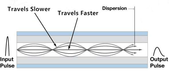
Generally, the maximum transmission distance is limited by the dispersion in fiber optic cables. There are two types of dispersion that can affect the optical transmission distance—chromatic dispersion and modal dispersion. Chromatic dispersion is the spreading of signals over time resulting from different speeds of light rays. Modal dispersion represents the spreading of the signals over time resulting from different propagation modes.
For single-mode fiber optic cable transmission, it is chromatic dispersion that affects the transmission distance. The reason is that the core of a single-mode fiber optic cable is much smaller than that of a multimode optical cable, and only allows one mode of light to propagate. Single-mode optical cable can transmit signals over longer distance than multimode optical cable. Multimode optical cable transmission is largely affected by modal dispersion, because these optical signals cannot arrive simultaneously and there is a delay between the fastest and the slowest modes, which causes the dispersion and limits the performance of multimode fiber optic cables, as shown in the following picture.
Fiber optic cable is the path for the transmission of optical signals. However, most of the terminals are electronic based, so the conversions between electrical signals and optical signals are very necessary. And this process largely depends on fiber optic transceivers, which are commonly used in most of today's fiber optic networks. LED (light emitting diode) or laser diode inside are the light sources of fiber optic transceivers, which can also affect the transmission distance of a fiber optic link.
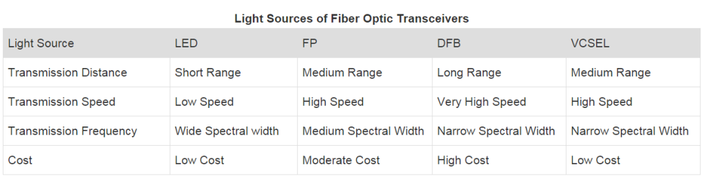
LED diode based transceivers can only support short distances and low data rate transmission. They cannot satisfy the increasing demand for higher data rates and longer transmission distances. For higher transmission data rates, laser diodes are used. Several commonly used laser sources in fiber optic transceivers are Fabry Perot (FP) laser, Distributed Feedback (DFB) laser and Vertical-Cavity Surface-Emitting (VCSEL) laser. For example, TRENDnet TEG-MGBSX SFP transceiver is a 1000BASE-SX SFP transceiver module with a VCSEL laser transmitter, which can support a data rate of 1.25Gbps and 550m transmission distance. The following table shows the main characteristics of these light sources.
Splices or connectors are inevitable in many fiber optic systems. Signal losses can be caused when optical signals pass through each splice or connector. The amount of the loss depends on the types, quality and number of connectors and splices. For example, signal loss through an LC LC multimode duplex fiber cable may not be the same with an ST ST multimode duplex fiber cable.
As mentioned in the above table, different laser sources support different frequencies. The maximum distance an optical system can support is also affected by the frequency at which the signals are transmitted. Generally the higher the frequency is, the longer distance the optical system can support. Thus, choosing the right frequency to transmit optical signals is quite necessary.
The bandwidth that fiber optic cable supports is another important factor that influences the transmission distance. As the bandwidth increases, the transmission distance usually decreases proportionally. For instance, a fiber that can support 100 MHz bandwidth at a distance of 5 kilometers will only be able to support 250 MHz at 2 kilometers and 500 MHz at 1 kilometer.
Optical transmission distance is limited by many factors, such as the type of fiber optic cable, light source of fiber optic transceiver, frequency of transmission, splices and connectors and bandwidth that the network supports. All these factors need to be taken into consideration during the deployment of fiber optic networks to minimize the limitations on the transmission distance. To break the barriers that limit the transmission distance, there is still a long way to go.
Posted by: jowang at
02:07 AM
| No Comments
| Add Comment
Post contains 737 words, total size 6 kb.
June 27, 2016
A communication system usually uses a wire or cable to connect transmitting and receiving devices. Currently, there are mainly three cable types deployed in communication systems, which are twisted pair cables, coaxial cables and fiber optic cables. Each type has been widely utilized in communication networks. What's the difference between these three kinds of cables? This article will make a comparison between them.
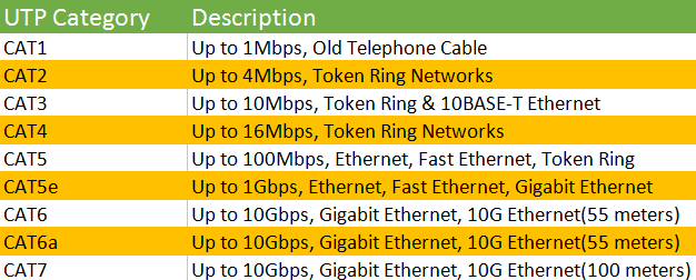
Twisted pair cable consists of a pair of insulated wires twisted together, which has been adapted in the field of telecommunication for a long time. With the cable twisting together, it helps to reduce noise from outside sources and crosstalk on multi-pair cables. Basically, twisted pair cable can be divided into two types: unshielded twisted-pair (UTP) cable and shielded twisted-pair (STP) cable. UTP cable, such as data communication cables and normal telephone cables, serves as the most commonly used cable type with merely two insulated wires twisted together. STP cable distinguishes itself from UTP cable in that it includes a foil jacket which helps to prevent crosstalk and noise from outside source. STP cable is typically used to eliminate inductive and capacitive coupling, and it can be applied between equipment, racks and buildings. The table below shows several different types of twisted pair cables.
Coaxial cable is a type of high-frequency transmission cable which contains a single solid-copper core. A coaxial cable has over 80 times the transmission capability of the twisted-pair cable. Coaxial cables are commonly used to deliver television signals and to connect computers in a network as well. There are mainly two kinds of coaxial cables: 75 Ohm coaxial cable and 50 Ohm coaxial cable.
75 Ohm coaxial cableThe primary use of 75 Ohm coaxial cables is to transmit video signals. One typical application of 75 Ohm coaxial cable is to transmit television signals over cable, which is why sometimes it is called signal feed cables. The most common connector type used in this application is a Type F. Another application is video signals between components, such as DVD players, VCRs or receivers commonly known as audio/video (A/V) cables. In this case, BNC and RCA connectors are often found. In both applications, RG59 with both solid center conductor (RG59B/U) and stranded center conductor (RG59A/U) as well as RG6 are common choices.
The primary use of 50 Ohm coaxial cables is the transmission of data signals in a two-way communication system. Several common applications for 50 Ohm coaxial cables are computer ethernet backbones, wireless antenna feed cables, GPS (Global Positioning Satellite) antenna feed cables and cell phone systems.
Computing and data communications are fast-developing technologies. To meet the transmission of ever-increasing data rates, there comes a new generation of transmission medium, which is fiber optic cable. Fiber optic cable transmits information using beams of light at light speed rather than pulses of electricity. It refers to the complete assembly of optical fiber. A fiber optic cable can contain one or more strands of optical fiber to transmit data. Each strand of optical fiber is individually coated by plastic layers and contained in a protective tube. Fiber optic cable transmits data as pulses of light go through tiny tubes of glass, the transmission capacity of which is 26,000 times higher than that of twisted-pair cable. When comparing with coaxial cables, fiber optic cables are lighter and more reliable for transmitting data.
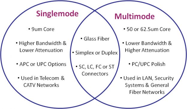
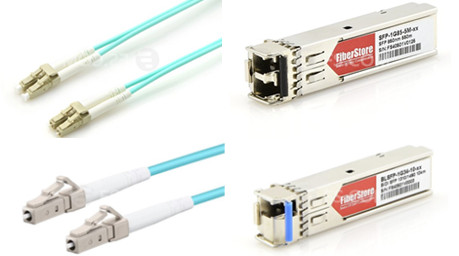
Two widely used types of fiber optic cables are single-mode fiber optic cables and multimode fiber optic cables. A single-mode optical fiber has a small core, and only allows one mode of light to propagate at a time. It is generally adapted to high speed and long-distance applications. A multimode optical fiber has a larger core diameter than a single-mode optical fiber and it is designed to carry multiple light rays, or modes at the same time. It is mostly used for communication over short distances because of its high capacity and reliability, serving as a backbone applications in buildings. And there are many connector types for fiber optic cable, such as LC, SC, ST or FC connector. You can choose fiber optic cables terminated at both ends with the same or different connector types to connect different devices, like LC SC fiber patch cable, LC to LC fiber patch cable. There are both single-mode and multimode, and simplx and duplex fiber optic patch cables for your options, such as LC to LC multimode duplex fiber optic patch cable, LC to SC duplex single-mode fiber optic patch cable, or LC LC multimode fiber patch cord.
As the technology in the field of network is developing rapidly, fiber optic cables seem to become the trend to meet the increasing demand of data rates in the market. However, whether to choose twisted pair cables, coaxial cables or fiber optic cables still depends heavily on applications. And other factors, such as the cost, transmission distance and performance, also need to be taken into consideration when making a choice.
Posted by: jowang at
08:52 AM
| No Comments
| Add Comment
Post contains 845 words, total size 7 kb.
June 24, 2016
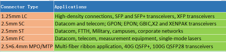
There are various fiber optic patch cables for different applications. Fiber optic jumper cables are available in OS1, OS2 single-mode types and OM1, OM2, OM3, OM4 multimode types. Fiber optic jumper cables are terminated on both ends with a high performance hybrid or single type fiber optic connector, such as SC, ST, FC, LC, MTRJ, or E2000 connector in simplex or duplex. How to choose right fiber optic patch cables for your networks? Here are 6 factors that you need to take into consideration.
A fiber optic patch cable is terminated on both ends with a fiber optic connector, such as LC connector, SC connector, ST connector, FC connector, or MPO/MTP connector. Different connectors are used to plug into different devices. If ports of devices in the both ends are the same, we can use fiber optic patch cables with the same type of connectors on both ends, such as LC LC cables, SC SC fiber patch cord, ST ST fiber patch cable, or MPO-MPO patch cables. If you want to connect different ports type devices, fiber optic patch cables with different types of connectors on both ends, like LC SC fiber patch cable, LC to ST fiber patch cable, or SC to ST fiber cable, may suit you.
Other than choosing the right connector type, you also need to choose the right connector polish type, whether the same polish type of the same connector type or different polish types of different connector types on both ends, such as SC APC fiber patch cord, SC/APC to LC patch cable. The loss of APC connectors is lower than UPC connectors. Usually, the optical performance of APC connectors is better than UPC connectors. APC connectors are widely used in applications such as FTTx, passive optical network (PON) and wavelength-division multiplexing (WDM) that are more sensitive to return loss. But APC connector is usually more expensive than UPC connector. With those applications that call for high precision optical fiber signaling, APC should be the first consideration, but less sensitive digital systems will perform equally well using UPC.
Fiber optic patch cable has two propagation modes: multi-mode and single-mode. Single-mode fiber patch cord uses 9/125um glass fiber. It is designed for the transmission of a single ray or mode of light as a carrier and is used for long-distance signal transmission. Multimode fiber patch cord usually uses 50/125um or 62.5/125um glass fiber. It can carry multiple light rays or modes, each at a slightly different reflection angle within the optical fiber core. Multimode fiber optic patch cables is used for relatively short distances because the modes tend to disperse over longer lengths. Typical single-mode fiber optic patch cable used yellow fiber cable and multi mode fiber optic patch cable used orange or aqua fiber cable.
Do you need simplex or duplex fiber optic patch cords? There is only one single strand of glass or plastic fiber in a simplex fiber optic patch cord. It is often used where only a single transmit and/or receive line is required between devices. A simplex fiber optic patch cord has only one fiber optic connector at each end, often used for Bidirectional (BiDi) fiber optic transceivers. A duplex fiber patch cord consists of two strands of glass or plastic fiber which are typically found in a tight-buffered and jacketed "zipcord" construction format. The duplex fiber is most often used for duplex communication between devices where a simultaneous and separate transmit and receive are required. Duplex fiber patch cords are used for common transceivers. Simplex and duplex fiber patch cords both are available in single mode and multi-mode.
Usually, there are three types of cable jacket: Polyvinyl Chloride (PVC), Low Smoke Zero Halogen (LSZH) and Optical Fiber Nonconductive Plenum (OFNP). You can see there features in figure below and choose the right one for your network.

Besides those three cable jacket types above, there is another common cable, armored cable. The double tubing and steel sleeve construction make these patch cables completely light tight, even when they are bent. These cables can withstand high crushing pressures, which makes them suitable for running along floors and other areas where they may be stepped on. The tubing also provides excellent cutting resistance, abrasion resistance, and high tensile strength.
Fiber optic jumper cables are made in different lengths, usually from 0.5m to 50m. You can choose an appropriate cable length according to the distance between the devices you want to connect.
When choosing a right fiber optic patch cord, you need to consider all these six factors carefully. Single-mode or multimode, simplex or duplex, APC or UPC connector polish type, which one is right for your networks? Which kind of fiber optic connector do you need, SC, ST, FC, LC, MTRJ, or E2000 connector? By figuring out what you need exactly and consider all these six factors, you can make appropriate choices for your applications.
Posted by: jowang at
07:00 AM
| No Comments
| Add Comment
Post contains 835 words, total size 7 kb.
June 20, 2016
When choosing fiber optic jumper cables, other than selecting the right connector type on both ends of the cable, such as SC to LC fiber cable, ST ST fiber patch cable, SC/APC to LC patch cable, SC to ST fiber cable, LC to ST fiber patch cable, or SC to SC patch cord, you also need to pay much attention to the construction of fiber optic cables. Nowadays, with increasing amount of cables found in residential, commercial and industrial applications, there is a greater fuel load in the event of a fire. Wire and cable manufacturers responded by developing materials that had a high resistance to fire while maintaining performance. Low-smoke, zero-halogen (LSZH) cables proved to be a key materials group that delivered enhanced fire protection performance. How much do you know about LSZH cables? This post aims at helping you learn more about LSZH fiber optic cables.
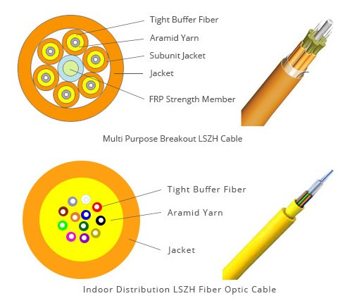
LSZH stands for low-smoke zero-halogen, and describes a cable jacket material that is non-halogenated and flame retardant. This type of jacket material has excellent fire safety characteristics of low smoke, low toxicity and low corrosion. When LSZH fiber optic cables (as shown below) come in contact with a flame, very little smoke is produced, making them ideal for applications where a lot of people are confined in a certain place, such as office buildings, train stations, airports, etc. A fire may be very harmful in a building, and at the same time, the smoke can cause even more damage to people who are trying to locate exits and inhalation of smoke or gases. LSZH fiber optic cables are free of halogenated materials like Fluorine (F), Chlorine (Cl), Bromine (Br), Iodine (I) or Astatine (At), and those materials are reported to be capable of being transformed into toxic and corrosive matter during combustion. Low-smoke property of LSZH fiber optic cables makes them safe and helpful. More people in fires die from smoke inhalation. LSZH fiber optic cables release low smoke and zero halogenated materials in these places would be really important to the safty of people.
There is no doubt that the amount of fiber optic cables installed in buildings has been increasing as data communication proliferates. LSZH fiber optic cables have been common in central office telecommunication facilities, due to the large relative fuel load represented by wire and cable. Several applications of LSZH fiber optic cables are:
- Public spaces like train stations, hospitals, schools, high buidings and commercial centers where the pretection of people and equipment from toxic and corrosive gases is critical.
- Data centers contain large amounts of cables, and are usually enclosed spaces with cooling systems that can potentially disperse combustion byproducts through a large area. Other materials burning may also contribute greater amounts of dangerous gases which will outweigh the effect of the cables. There have been notable fires where cables burning contributed to corrosion, but in some instances, better fire response techniques could have prevented this damage.
- Nuclear industry is another area where LSZH fiber optic cables have been and will be used in the future. Major cable manufacturers have been producing LSZH fiber optic cables for nuclear facilities since the early 1990s. The expected construction of new nuclear plants in the U.S. in coming years will almost certainly involve LSZH fiber optic cables.
No two products are the same and many factors will define the suitability of the final product to its application. Research shows that 27 LSZH compounds have huge variation in physical properties. Even using material which meets the base requirements of one of the many specifications available may not result in the best material for the application. When choosing LSZH fiber optic cables, factors such as the environment and price should be considered. An environmental factor such as the temperature of the installation could reduce the flexibility of the cable. Will the application be in an open area or confined? Will other flammable material be present? Many factors need to be taken into consideration. LSZH fiber optic cables also tend to be higher in cost.
When selecting or designing a fiber optic cable or fiber optic jumper cable for any application, the operating enviroments where the fiber optic cable will be used, whether extreme or not, must be considered along with availability, performance, and price. And when the safety of humans and the enviroment is a consideration, along with high-performance and capability, LSZH fiber optic cables provide a good solution for you.
Posted by: jowang at
04:30 AM
| No Comments
| Add Comment
Post contains 760 words, total size 6 kb.
June 17, 2016
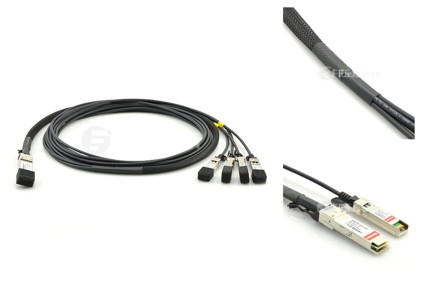
When talking about direct attach cables, we may come across breakout cable, such as Cisco QSFP+ breakout cable. There are many kinds of breakout cables, and they are suitable for various applications. For example, a Cisco QSFP-4SFP10G-CU5M compatible QSFP+ to 4 SFP+ passive direct attach copper breakout cable, as shown below, connects to a 40G QSFP+ port of a Cisco switch on one end and to four 10G SFP+ ports of a Cisco switch on the other end, and is used for very short distances and offers a very cost-effective way to connect within racks and across adjacent racks. Other than copper breakout cable, there is also fiber breakout cable. What is fiber breakout cable? How much do you know about fiber breakout cable? In this post, a brief introduction to fiber breakout cable will be given.
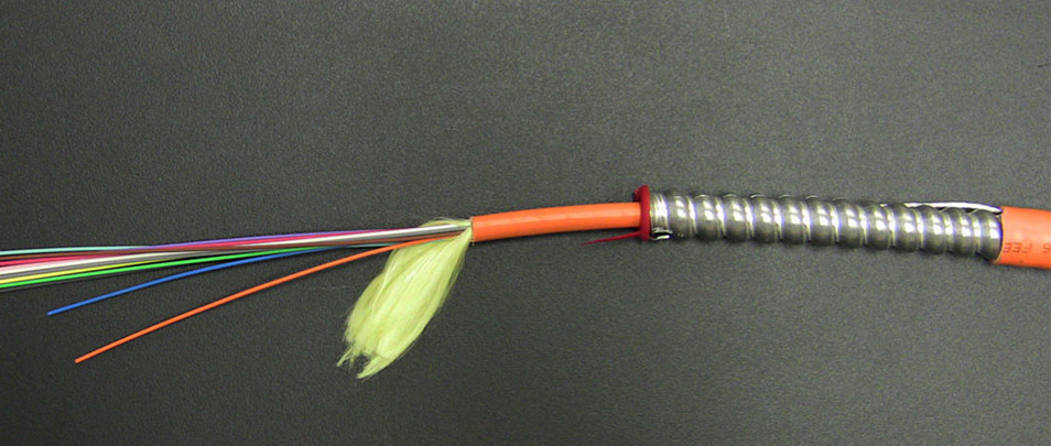
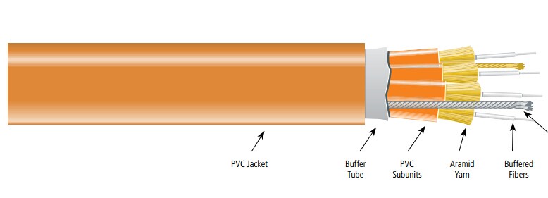
Breakout-style fiber optic cable, also called fiber breakout cable or fiber fan-out cable, is an optical cable which contains several jacketed simplex optical fibers package together inside an outer jacket. It differs from a distribution-style cable, in which tight-buffered fibers are bundled together, with only the outer cable jacket of the cable protecting them. The design of breakout-style cable adds strength for ruggedized drops, however the cable is larger and more expensive than distribution-style cable. The structure of fiber breakout cable (shown as the figure below) ensures a long life. A fiber breakout cable consists of outer jacket, tap binder, breakout fiber assembly (tight-buffered fiber surrounded in aramid yarns and jacketed), strength member, and ripcord. For easier handling, it also features an easily strippable 900µm coating. Both the PVC and plenum cables are rated for fire safety.
- The key purpose of fiber breakout cable is that one can "break out" several fibers at any location, routing other fibers elsewhere.
- Each numbered fiber sub unit is protected by a layer of aramid yarn and encased in a FRNC/LSNH jacket. The individual sub units are cabled and then jacketed with a flame resistant FRNC/LSNH compound. Each fiber uses either the tight buffer technology or semi-tight buffer technology for excellent fiber stripping.
- Each fiber of a breakout cable has its own jacket and aramid strength elements, so each fiber is extremely strong and rugged.
- Fiber breakout cable is available in a variety of designs that will accommodate the topology requirements found in rugged environments. Fiber counts from simplex to 256 are available.
- A tight buffer design is used along with individual strength members for each fiber. This permits direct fiber cable termination without using breakout kits or splice panels.
- Due to the increased strength of Kevlar members, fiber breakout cables are heavier and larger than the telecom types with equal fiber counts.
- A fiber breakout cable offers a rugged cable design for shorter network designs. This may include LANs, data communications, video systems, and process control environments.
- Fiber breakout cable is extremely versatile and suitable for use in riser and plenum indoor applications. You can use it in backbone and horizontal runs.
- Each fiber is individually reinforced, so you can divide a breakout cable into individual fiber lines, which enables quick connector termination and eliminates the need for patch panels.
- Fiber breakout cable can be more economical because it requires much less labor to terminate. You may want to choose a cable that has more fibers than you actually need in case of breakage during termination or for future expansion.
- Fiber breakout cable offers advantages over standard patch cords because it eliminates the need for a fiber-optic ducting system.
Fiber breakout cables are typically used for indoor applications, between an optical distribution frame and an electronic equipment rack, or between two electronic equipment racks. These cables are particularly effective when equipment racks are distributed over a large area (for example several floors in a large building). The end of the breakout cable behaves like a standard single pigtail. The outer jacket of the cable can be stripped. Fiber breakout cables are used to carry optical fibers that will have direct termination to the equipment, rather than being connected to a patch panel. Covered with an outer jacket, these cables are ideal for routing in exposed trays or any application requiring an extra rugged cable that can be directly connected to the equipment. And they are also suitable for pre-terminated cable assemblies.
Fiber breakout cables are ideal for installations requiring an extremely rugged and reliable cable design where maximum mechanical and environmental protection are necessary. And fiber breakout cables have many obvious advantages, such as cost savings, direct termination to sub cable, which eliminates the need for patch panels and patch cords and reduces connector loss, and easy installation and high crush resistance.
Posted by: jowang at
02:34 AM
| No Comments
| Add Comment
Post contains 802 words, total size 7 kb.
June 15, 2016
SFP+ direct attach copper cable assembly is a high speed and cost-effective alternative to fiber optic cables in 10G Ethernet applications. 10g copper SFP is suitable for short distances, and ideal for highly cost-effective networking connectivity within a rack and between adjacent racks. It enables hardware OEMs and data center operators to achieve high port density and configurability at a low cost and reduced power requirement. SFP+ direct attach copper cable has been a good solution. This post will provide you with some basic information about SFP+ direct attach copper cable.
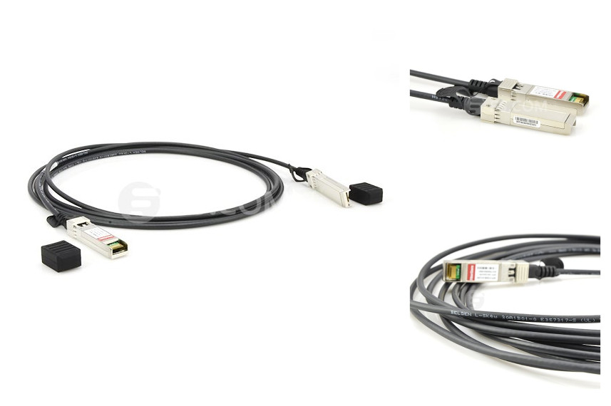
SFP+ direct attach copper cable, also known as twinax cable, is an SFP+ cable assembly used in rack connections between servers and switches. It consists of a high speed copper cable and two SFP+ copper modules. SFP+ copper modules allow hardware manufactures to achieve high port density, configurability and utilization at a very low cost and reduced power budget. SFP+ copper cable assemblies meet the industry MSA for signal integrity performance. The cables are hot-removable and hot-insertable, which means that you can remove and replace them without powering off the switch or disrupting switch functions. A cable comprises a low-voltage cable assembly that connects directly into two SFP+ ports, one at each end of the cable. The cables use high-performance integrated duplex serial data links for bidirectional communication and are designed for data rates of up to 10 Gbps. The following picture shows a Cisco SFP-H10GB-ACU7M compatible 10G SFP+ direct attach copper twinax cable.
Generally, SFP+ direct attach copper cable assemblies have two types, SFP+ active direct attach copper cable and SFP+ passive direct attach copper cable.
SFP+ Active Copper Cable: SFP+ active direct attach copper cable assemblies contain low power circuitry in the connector to boost the signal and are driven from the port without additional power requirements. The active version provides a low cost alternative to optical transceivers, and are generally used for end of row or middle of row data center architectures for interconnect distances of up to 15 meters.
SFP+ Passive Copper Cable: SFP+ passive direct attach copper cable assemblies offer high-speed connectivity between active equipment with SFP+ ports. The passive assemblies are compatible with hubs, switches, routers, servers, and network interface cards (NICs) from leading electronics manufacturers like Cisco, Juniper, etc.
- Serial data transmission
- Network Interface Cards (NICs)
- Data center cabling infrastructure
- Fibre Channel over Ethernet: 1, 2, 4 and 8G
- 10Gb Ethernet and Gigabit Ethernet (IEEE802.3ae)
- High density connections between networking equipment
- High capacity I/O in storage area networks, and storage servers
- InfiniBand standard SDR (2.5Gbps), DDR (5Gbps) and QDR (10Gbps)
- Switched fabric I/O such as ultra high bandwidth switches and routers
1. Whether active or passive cable assemblies are required?
Active cable assemblies have signal amplification and equalization built into the assembly. They are typically used in host systems that do not employ EDC. Passive cables have no signal amplification in the assembly and rely on host system Electronic Dispersion Compensation (EDC) for signal amplification/equalization.
2. What are the performance requirements for the cable assembly?
Both SFP+ active and passive copper cable assemblies should meet the signal integrity requirements defined by the industry MSA SFF-8431.
3. What cable length and wire gauge are required?
Cable length and wire gauge are related to the performance characteristics of the cable assembly. Longer cable lengths require heavier wire gauge, while shorter cable lengths can utilize a smaller gauge cable. Smaller wire gauges results in reduced weight, improved airflow and a more flexible cable for ease of routing.
4. Are there any special customer requirements?
Examples of special customer requirements include: custom cable lengths, EEPROM programming, labeling and packaging, pull tab length and color, company logo, signal output de-emphasis, and signal output amplitude. You can order custom cables to your specific system architecture.
Fiberstore SFP+ twinax copper cables are available with custom version and brand compatible versions. All of them are 100% compatible with major brands like Cisco, HP, Juniper, Enterasys, Extreme, H3C and so on. Both passive twinax cables in lengths of 1, 3 and 5 meters, and active twinax cables in lengths of 7 and 10 meters are available. And the lengths can be customized up to the your requirements. You can get high quality compatible SFP+ cables and worldwide delivery from Fiberstore.
Posted by: jowang at
01:53 AM
| No Comments
| Add Comment
Post contains 739 words, total size 6 kb.
June 13, 2016
As we know, fiber optic connectors are essential components in iber optic networks. They are terminated at one end or both ends of a fiber optic cable, enabling a quick and efficient connection between fiber optic equipment. To make sure a fiber optic jumper cable, such as LC to LC cable, SC to LC cable, or SC to SC patch cord, can function well, fiber optic connector cleaning becomes one of the most important thing in the process of fiber optic system maintenance, which is required to keep quality connections between fiber optic equipment. How to clean a fiber optic connector? This post will provide you with some basic knowledge about fiber optic connector cleaning.
Fiber optic connector consists of fiber optic plug and the adapter. The ends of a fiber optic cable are held in the core of the ferrule in the plug. Keeping the fiber end face and ferrule absolutely clean is very essential, since any particles such as dust, oil or lint on the end face of the fiber will disrupt the light transmission trough the fiber and lead to the incompleteness of optical signals for the component or the entire system. For example, for proper performance of the SC SC fiber patch cord, you must keep the SC connector clean and free of dust. Small micro-deposit of oil and dust in the canal of the connector could cause loss of light, signal power loss and possible intermittent problems with the optical connections.
- 1. Before cleaning fiber optic connectors, make sure to disconnect the fiber optic jumper cables from both ends and then turn off the laser source.
- 2. Do not make the end of the fiber optic cable to contact with any surface including your fingers.
- 3. Never to bend the fiber optic cable, which will in turn cause internal breaks along the fiber and cause poor performance or instability.
- 4. Use the finger cots or powder free surgical gloves to handle fiber optic cables.
- 5. Use fresh spectroscopic grade methanol or isopropyl alcohol as the cleaning solvent.
- 6. In the daily connection work, a connector housing should be used when plugging or unplugging a fiber, and a protective cap should be used to cover the unplugged fiber optic connectors.
- 7. During the process of a fiber optic connector cleaning, the end face of the connector should never be touched and the clean area of a tissue of swab should not be touched or reused.
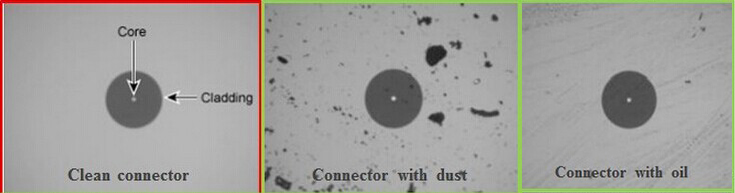
At the beginning of the cleaning job, a fiber microscope should be used to inspect the fiber end. If the fiber end is contaminated as the following image shows, it should be cleaned, and the cleaning procedures are:
- 1. Blow the fiber surface with a stream of Clean Dry Air (the so called CDA), which will dislodge larger, loose particles. Keep in mind, don't tip the can of the CDA while blowing, because the liquid may be released contaminant on the surface of the fiber.
- 2. Place 1-3 drops of spectroscopic grade methanol or isopropyl alcohol in the center of a lens tissue. Do not use acetone as a cleaning solvent on the fiber optic surfaces. Besides, to ensure the purity of the methanol or alcohol, you should never insert the lens tissue or swabs into the liquid.
- 3. Hold the fiber by the connector. Place the wet portion of the lens tissue on the optical surface and slowly drag it across. Don't use lens paper to dry it because the dry lens paper is extremely abrasive.
- 4. Examine the surface of the fiber under high density light using a magnifier, an optical loop, or a video inspection tool. If streaks or contaminants still remain, repeat the process using a fresh lens tissue.
- 5. Immediately install a protective cover over the end of the cable to avoid re-contamination or insert the fiber for immediate use.
Fiber optic connector cleaning process is a very necessary and critical process. A fiber optic connector should be properly cleaned and maintained to ensure optimum reliability and system performance. It is not just important to have the proper tools for the job, but also know when to use them and how to use them. Fiber optic cleaning kit such as the Cletop Reel Type cleaner, Cartridge-Type cleaner, OAM connector cleaners are all good solutions, all of which you can get from Fiberstore. Just follow the instructions for each cleaning kit you will use.
Posted by: jowang at
03:42 AM
| No Comments
| Add Comment
Post contains 750 words, total size 5 kb.
June 08, 2016
SFP (small form-factor pluggable) was jointly developed by many of the world's leading network vendors. It has been widely used in optical network systems. Nowadays, many 3rd party SFP module vendors are providing high quality and reliable compatible SFP transceiver modules with low prices, such as compatible Cisco gigabit SFP, and using 3rd party SFP modules seems to be more and more popular now. Whether to choose compatible SFP modules or not? Here are some common questions that you might ask when using compatible SFP transceivers. Hope these answers can help you get a better understanding of compatible SFP modules.
1000BASE-T is Gigabit Ethernet on copper cables, using four pairs of Category 5 unshielded twisted pair to achieve the gigabit data rate. 1000BASE-T can be used in data centers for server switching, for uplinks from desktop computer switches, or directly to the desktop for broadband applications. A big advantage of 1000BASE-T is that existing copper cabling can be used instead of having to rewire with optical fiber. 1000BASE-X is a group of standards for Ethernet physical layer standards, specified within the IEEE 802.3.z standard. It is used for Gigabit Ethernet connections that transmit data mainly over fiber optic cable. The standards that apply to the term 1000BASE-X include -LX, -SX, -BX10, -LX10, as well as non-standard -ZX and -EX standards. All of the standards that are grouped at 1000BASE-X utilize a 8b/10b encoding where 8 bits are reserved for data transmission while 2 bits are used for error correction.
Each module holds its own information in EEPROM, and this memory is coded with unique identifiers such as part numbers and manufacturers details. The firmware of the host device then checks the memory for the correct information to confirm compatibility.
This is a common problem, a large amount of host devices do not have a firmware check for compatibility, this is known as an "open platform". Many SFP transceivers are sold as compatible when in fact they are open platform. They will work in many host devices but not in any that require coded transceivers. OEM SFP transceivers are coded specifically to suit each host device to avoid this problem, such as HP J4859C (as shown below) and HP JD118B SFP modules.
No, host device warranty will be unaffected. Please note that host device warranties do not cover SFP transceiver modules, OEM vendors offer lifetime warranties to protect them.
DOM, short for digital optical monitoring, is a feature used to monitor some parameters of the transceiver in real-time, helping to identify the location of the fiber link failure, simplify maintenance, and improve system reliability. DOM allows you to monitor the TX (transmit) and RX (receive) power of the module, temperature, and transceiver supply voltage. With DOM, network administrators can check and ensure that the module is functioning correctly in an easy and convenient way. This is why most of modern optical SFP transceivers support DOM functions.
In fact, most of the networking manufacturers do not produce their own SFP, XFP, SFP+, X2 transceivers, etc. They buy OEM transceivers, label them with their own brand and sell at a much higher price. You are basically paying a high price to have the respective manufacturers logo on the equipment. Besides, many compatible transceivers are made and assembled in exactly the same plants assembling officially-branded transceivers. There is almost no big difference between an official transceiver and a third-party plug, aside from the branding and about two hundred to a few thousand bucks.
Here are three methods. First one is appearance recognition. Check the appearance of the SFP module. A new SFP module's appearance generally has good consistency while a refurbished SFP module is not glossy, and has some wear and scratches in the rim angle. Many refurbished SFP modules are replaced with new shells. If there is dust in the interface or the interface is not smooth, it is refurbished SFP module. Then you can check the ferrule. Pulling out the dust cap, you can see the ferrule in the bore. A second-hand old module is not glossy, and generally rough and with scratches, and it has a bad consistency. The ferrules of a new quality module is bright with color and lustre and has a good consistency. Last, you can put the module under the status of 50-60°C and see whether it can work properly. In general, a refurbished SFP module can not work well or even disconnect.
Various vendor-coded SFP modules are compatible to widespread networking equipment from well-known manufacturers. Fiberstore provides a variety of SFP transceiver modules that are compatible to devices of important vendors in the market. From production to shipmet, all these compatible SFP modules are tested and guaranteed 100% compatible and with high qulity.
Posted by: jowang at
02:05 AM
| No Comments
| Add Comment
Post contains 847 words, total size 6 kb.
June 06, 2016
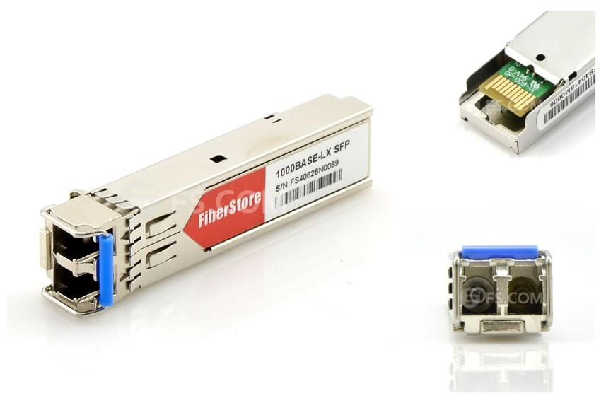
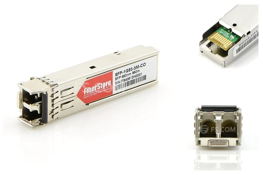
Optical transceiver module is a device which can transmit and receive light and electrical signals in fiber optic networks. An optical transceiver generally has two ports, one for converting electrical signal into light signal and the other for changing light signal into electrical signal. Based on different data rates, there are many different kinds of transceiver modules, such as SFP (small form-factor pluggable), SFP+ (small form-factor pluggable plus), QSFP+ (quad small form-factor pluggable plus), CFP (C form-factor pluggable). Among them, SFP optical transceiver is a compact and hot-pluggable transceiver widely deployed for the Fast Ethernet and Gigabit Ethernet, for example, Cisco GLC-SX-MM compatible 1000BASE-SX SFP transceiver, as shown below, can support data rate up to 1000Mbps. In this post, a brief introduction to several commonly used SFP transceivers will be given.
Coarse wavelength division multiplexing (CWDM) SFP is made up of three parts: an uncooled laser transmitter, a PIN photodiode integrated with a trans-impedance preamplifier and a MCU control unit. It is an economical technique to save fiber resources through transmitting multiple wavelengths on one optic fiber. CWDM SFP is a kind of single-mode transceiver used for Gigabit Ethernet and Fibre Channel applications. The wavelengths of CWDM SFP are between 1470nm and 1610nm distinguished by different colors. Most commonly used CWDM SFP transceivers include CWDM SFP 1470, CWDM SFP 1490, CWDM SFP 1510, CWDM SFP 1530, CWDM SFP 1550, CWDM SFP 1570, CWDM SFP 1590, and CWDM SFP 1610, etc. CWDM SFP can support high performance of 1.25Gbps data rate and 80km transmission distance.
Dense wavelength division multiplexing (DWDM) SFP is a type of hot-pluggable transceiver used for Gigabit Ethernet which gathers different wavelengths onto one single fiber. Compared with CWDM SFP, DWDM SFP has a more intensive wave spacing for a high performance of data communication. The working wavelength of DWDM SFP ranges from 1525nm to 1565nm or 1570nm to 1610nm. The wave intervals are varied in 0.4 nm, 0.8 nm, 1.6 nm, etc. And the port of DWDM SFP transceiver uses SFP interface for over 1 gigabit optical data transmission.
BiDi SFP is short for Bi-Directional SFP. The core technology of BiDi SFP transceiver is the BiDi technique which enables bidirectional transmission of two different waves. BiDi module has only one port, and it must be deployed in pairs. For example, when a BiDi SFP module is used for receiving 1310nm and transmitting 1550nm optical signals, the other should receive 1550nm and transmit 1310nm signals, and vice versa. BiDi SFP transceiver usually costs twice the price of common SFP transceivers, but it is a better way to save the expenditure spent on optical fiber. BiDi transceivers have the advantage of reducing fiber cabling infrastructure costs by lowering the number of fiber patch panel ports, decreasing the amount of tray space dedicated to fiber management, and using less fiber cable.
Fibre Channel (FC) SFP uses the technology of fiber channel for high speed optical signal transmission with a data rate up to 4.25 Gbps. Fiber channel is a mature technology for serial interface standardized by American National Standards Institute (ANSI). It is applied to the connection between the storage controller and computer drivers. Nowadays, FC has played as a replacement for the Small Computer System Interface (SCSI) in high-performance storage systems, because fiber channel is faster in transmission speed and more flexible in the transmitting mode with or without fiber in accordance with the transmission range.
Synchronous optical networking (SONET) SFP or synchronous digital hierarchy (SDH) SFP is a kind of transceiver based on the SONET/SDH standard. SONET/SDH is the physical standard for fiber optic transmission, first brought out by Bellcore in 1980s and then standardized by American National Standards Institute (ANSI) for popularization all over the world. SONET/SDH standard mainly stipulates the transmission rate, fiber interface, operation and maintenance in optical fiber transmission. SONET/SDH SFP transceivers can support OC-3 (up to 155.52 Mbps), OC-12 (up to 622.08 Mbps), and OC-48 (up to 2488.32 Mbps) data rates for multimode, short-reach, intermediate-reach, and long-reach applications.
SFP modules are found in Ethernet switches, routers, firewalls and network interface cards. With advantages of low cost, low profile, and the ability to provide a connection to different types of optical fiber, SFP modules provide the related equipment with enhanced flexibility. SFP transceivers are hot-pluggable small form factors used for 100BASE and 1000BASE Ethernet data transmission. There are different types of SFP modules, including BiDi SFP, CWDM SFP, DWDM SFP, SONET/SDH SFP and FC SFP. Each of them supports different techniques, which brings convenience to data communication.
Posted by: jowang at
03:29 AM
| No Comments
| Add Comment
Post contains 769 words, total size 6 kb.
June 03, 2016
Deploying fiber optic jumper cables is just the first step to meet the high-bandwidth requirements, and efficient and strong management over those fiber optic patch cords is the basic requirement for a successful fiber optic network infrastructure. To deliver and guarantee the optimal network performance, fiber patch cable management is critical. Good management can lower operation cost and time, and increase the reliability and flexibility of network operation and maintenance. This post will help you better understand fiber patch cable management.
To get a flexible and well-organized fiber patch cable management, you need to take several factors into consideration.
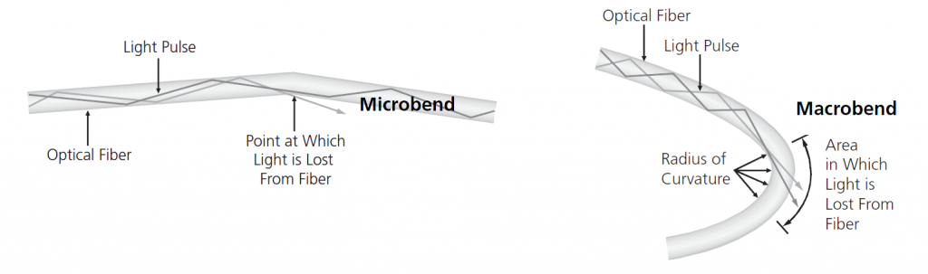
Bend RadiusCompared with copper, optical fiber, usually made of glass, is much more fragile and need more protection and attention during the operation and management. Bend radius of an optical fiber will impact its reliability and performance. If a fiber cable is bent excessively, optical signals within the cable may refract and escape through the fiber cladding, causing loss of signal strength, also known as bend loss. Bending, especially during the installation and pulling of fiber optic patch cable, may also cause micro cracks and damage the fiber permanently. There are generally two basic types of bends, which are microbends and macrobends, as shown in the following picture.
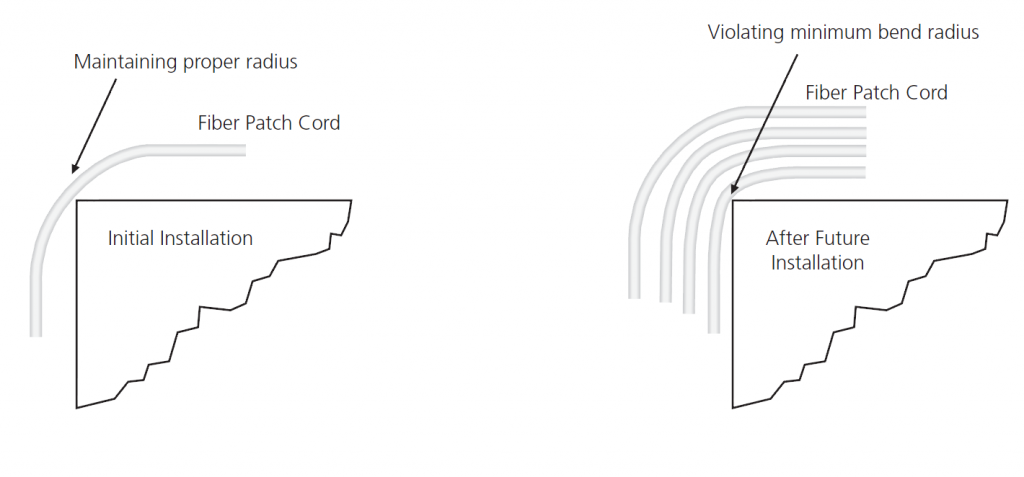
Note that bend radius might not be seen during the initial installation of fiber patch cables. Because the number of fiber patch cables routed to the optical distribution ODF is usually small. When more fiber patch cords are added on the top of installed fiber patch cables later, problems will show up (shown in the following picture). A fiber patch cable which works fine for years might suddenly have an increased level of attenuation, as well as a potentially shorter service life.
Fiber patch cable path, which can affect the performance and maintenance of fiber patch cables, is an aspect closely related to bend radius. The path of fiber patch cable should be clearly defined and easy to follow. Improper cable routing can cause increased congestion in the termination panel, increasing the possibility of bend radius violations and long-term failure. Well managed fiber patch cable path ensures that bend radius requirements are maintained at all points and makes access to individual fiber patch cable much easier, quicker and safer, especially for those fiber patch cables with different types of connectors on the two ends, such as SC to LC fiber cable, or LC to ST fiber patch cable. Well-organized fiber patch cords can also help to decrease operating costs and the time required to turn-up or restore service.
Accessibility of Fiber Patch CableAccessibility of the installed fiber patch cable is also a factor that you need to take into consideration. If installed fiber patch cables are easy to access, the maintenance and operation would be quick without inducing a macrobend on an adjacent fiber, and it can also offer proper bend radius protection. Accessibility is critical during network reconfiguration operations and directly impacts operation costs and network reliability.
According to those mentioned aspects which can affect the performance and maintenance of fiber optic patch cables, here are several tips that can help to increase the performance of fiber patch cords and the reliability and flexibility of fiber patch cable management.
- 1. Pay attention to the bend radius of fiber patch cables. Generally, for 1.6mm and 3.0mm fiber patch cords the minimum un-loaded bend radius is 3.5cm. The minimum bend radius of MPO cable is ten times the cord diameter.
- 2. Never pull or stress fiber patch cords. During the patching process, excessive force can stress fiber patch cables and connectors attached to them, thus reducing their performance. There might be something wrong if you need to use force in pulling a cord.
- 3. Routing fiber patch cords through cable pathways, so as to ensure there are no tangles, kinks or strains in the cords. For efficient routing, find the best path between the ports to be connected, avoiding routing cords through troughs and guides that are already congested.
- 4. Bundling and tying fiber patch cords gives the panel a neat appearance but tight bundling increases the risk of pinching. Do not tighten cable ties beyond the point where individual cord can rotate freely.
- 5.Labeling is necessary. At any administration point in a cabling infrastructure, including patching panels, accurate labels are essential. These will identify pair modularity and tell technicians where the other end of the cable is terminated.
- 6. Inspect fiber patch cords for physical damage including stress marks from sharp bends on the sheath, or damage to connectors.
A successful fiber patch cable management can increase the reliability and flexibility and decrease the cost of network operation and maintenance. To achieve successful fiber patch cable management, you need to consider and ensure bend radius protection, reasonable patch cable paths, and easy accessibility to fiber patch cables. When those factors are satisfied, it is already half the success to strong fiber patch cable management.
Posted by: jowang at
02:59 AM
| No Comments
| Add Comment
Post contains 843 words, total size 7 kb.
June 01, 2016
Optical fiber is now an effective high-capacity data communication medium for it can support long distance transmission. It is a fiber constructed of glass or plastic, which does not contain any metal material and thus avoids Electro-Magnetic Interference (EMI) and distortion of information along with the distance. This results in high accuracy of data along the transmission cable. The data is modulated within the light waves. There are mainly two modes of cables available: single-mode and multi-mode. Multi-mode patch cord is multi-mode fiber cable terminated at both ends with fiber optic connectors. In this article, detailed information about multi-mode patch cords will be given to help you get a better understanding of them.
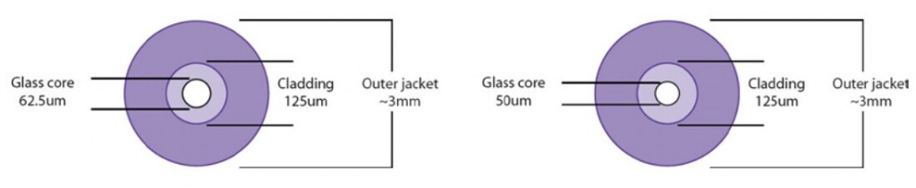
Multi-mode patch cord is usually 50/125 and 62.5/125 microns in construction (shown in the following figure). The numbers 50 μm and 62.5 μm refer to the diameters of the glass or plastic core, the part of the fiber that carries the light which encodes your data. The number 125μm is the diameter of the cladding, which confines the light to the core because it has a lower index of refraction. The transition between the core and cladding can be sharp, which is called a step-index profile, or a gradual transition. The two types have different dispersion characteristics and thus different effective propagation distance. Multi-mode fiber cables may be constructed with either graded or step-index profile, and those with graded index fiber is better in accuracy and performance.
Multi-mode patch cord has a larger core diameter than single mode patch cable, allowing multiple modes of light to propagate. Due to this, the number of light reflections created as the light passes through the core increases, creating the ability for more data to pass through at a given time. Multi-mode patch cord has high dispersion and attenuation rate, which means the quality of the signal is reduced over long distances. Multi-mode patch cord is typically used for short distance transmission, for usually a distance less than 500 meters, such as data and audio/video applications in local area networks (LANs).
Multi-mode fiber optic cable is described using a system of classification determined by the ISO 11801 standard—OM1, OM2, and OM3—based on the modal bandwidth of multi-mode optical fiber. OM4, defined in TIA-492-AAAD by the TIA, was finalized in 2009. "OM" stands for optical multi-mode. Technically, OM1/OM2/OM3/OM4 multi-mode fiber did not define a specific fiber size, but rather their optical channel performance.
OM1 specifies 62.5μm fiber core size and OM2 specifies 50μm fiber core size. They are commonly used in premises applications supporting Ethernet rates of 10 Mbps to 1 Gbps, not suitable enough for today's higher-speed networks. They were ideal for use with LED transmitters. OM3 and OM4 specify an 850nm laser-optimized 50μm cable. They are both laser-optimized multi-mode fiber (LOMMF) and were developed to accommodate faster networks such as 10 Gbps, 40 Gbps, and even 100 Gbps. OM1/OM2/OM3/OM4 can sometimes be distinguished by jacket color: orange jackets for 62.5/125μm OM1 fiber and 50/125μm OM2 fiber, and aqua is recommended for 50/125μm "laser-optimized" OM3 and OM4 fiber.
Both OM3 and OM4 are laser-optimized high bandwidth 50µm multi-mode fiber. The requirements of the OM4 standard are identical to OM3 with the sole exception of the bandwidth values. Both 850nm EMB and 850nm over-filled launch (OFL) bandwidth have been increased from the OM3 requirements. OM3 with a effective modal bandwidth of 2000 MHz·km and OM4 with an effective modal bandwidth of 4700 MHz·km. Laser optimized 50µm multi-mode fiber is the recommended fiber type in today's LAN and data center environments in conjunction with 850nm vertical-cavity surface-emitting lasers (VCSELs). For prevailing 10Gb transmission speeds, OM3 is generally suitable for distances up to 300 meters, and OM4 is suitable for distances up to 550 meters. With the spread of 40 and 100 Gigabit Ethernet, OM3 and OM4 also are only well positioned to support these burgeoning data rates over distances of 100m and 150m respectively. OM4 supports the majority of data center links that utilize 40 and 100 GbE in high-speed/high-performance computing applications driven by server virtualization, cloud computing, streaming video, and ever increasing IP traffic and convergence.
Multi-mode patch cord is a commonly used fiber optic jumper type for short distance transmission. And there are mainly four different kinds of multi-mode patch cord, OM1 multi-mode patch cord, OM2 multi-mode patch cord, OM3 multi-mode patch cord, and OM4 multi-mode patch cord. These four kinds of multi-mode patch cords have their own special applications. You can choose from according to your own needs.
Posted by: jowang at
02:28 AM
| No Comments
| Add Comment
Post contains 773 words, total size 6 kb.
32 queries taking 0.0765 seconds, 86 records returned.
Powered by Minx 1.1.6c-pink.

