


April 29, 2016
Fiber optic patch cable, or fiber jumper, is a very basic and important part used to connect equipment and components in fiber optic networks. There are many kinds of fiber optic patch cables, such as single-mode fiber patch cable, multimode fiber patch cable, 10G OM3 fiber patch cable, 10G OM4 fiber patch cable, MPO cable, and a lot of special fiber patch cables for special applications, like military grade fiber cable, plastic optical fiber patch cables, mode conditioning patch cable, volition fiber patch cables, etc. Different kinds of fiber optic patch cables are used for different applications. Among all those fiber jumpers, how to make a right choice? This post will give you a selection guide from several aspects.
According to the core sizes of the fiber, fiber optic patch cables can be divided into single-mode fiber optic patch cable and multimode fiber optic patch cable. Single-mode fiber patch cable uses a single strand of glass fiber for a single ray of light transmission, allowing for greater signal distances. The power of single-mode fiber patch cable comes from high-powered lasers which transmit data at longer distances than multimode fiber patch cable. Multimode fiber optic patch cables have a core of either 50 or 62.5 microns. The larger core of multimode fiber patch cords gathers more light compared to single mode, and allows more signals to be transmitted. Light waves in the multimode fiber patch cable are dispersed into numerous paths as they travel through the cable core. Therefore, multimode fiber patch cable cannot travel as far as single-mode fiber optic patch cable. Multimode fiber patch cables are usually used for short distance applications, such as connections within the data center. Multimode fiber optic patch cable is available in several performance levels to support a variety of distances: OM1 applies to a large portion of the installed legacy systems; OM2 supports Gigabit Ethernet up to 550m; OM3 is laser-optimized to support 10G Ethernet up to 300m; and OM4 is also laser-optimized to support 10G Ethernet up to 550m.
Simplex fiber optic patch cable has a single strand of fiber and one connector on each end. Duplex fiber optic patch cable has two strands of fibers and two connectors on each end of the cable. Duplex fiber optic patch cable is the more popular patch cable type as most fiber electronics need two fibers to communicate, one to transmit data signals, and the other to receive signals. But in a few applications, only one fiber is needed, so simplex fiber optic patch cable is good for you. If you are not sure, you can always be on the safe side by ordering duplex fiber optic patch cables, and only using one of the two fibers.
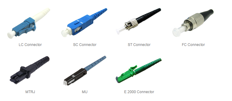
Fiber optic patch cable types can also be classified by the fiber optic connectors. They can be terminated with a variety of connector types such as LC, SC, FC, ST, MU, MTRJ, E200, etc. Connectors on both ends of a fiber jumper can be the same and can also be different. Fiber optic connectors have different constructions and their respective applications. For example, LC connector is a small form factor plastic push/pull connector with a 1.25mm ferrule, and it has a locking tab and a plastic housing and provides accurate alignment via its ceramic ferrule; FC connector is a metal screw on connector with a 2.5mm ferrule, and it is extensively used at the interfaces of test equipment due to its ruggedness. So when selecting a fiber optic patch cord, one important criterion to consider is to choose one with the most appropriate connector type that meets your needs.
Fiber optic patch cables will be used in a variety of installation environments, thus there will be requirements for the jacket materials. The standard jacket type is called OFNR (optical fiber non-conductive riser) which contains no metal in it, conduct stray electric current, and can be installed in a riser application (going from one floor up to the next, for instance). OFNR cable jacket is also known as plenum jackets, which are suitable for plenum environments such as drop-ceilings or raised floors. Many data centers and server rooms have requirements for plenum-rated cables. Another jacket type is LSZH (low-smoke zero-halogen), which is made from special compounds which gives off very little smoke and no toxic halogenic compounds when burned and is being used in many public places, like schools, hospitals, train stations, etc.
Knowing the special applications of each kind of fiber jumper and the desired capabilities is what you need to do before jumping to a decision. Your choice will affect the level of fiber protection, ease of installation, splicing or termination, and even the whole cost of the project. How to select the fiber optic patch cord that you need exactly? You need to take all those mentioned factors into consideration, single-mode or multimode, simplex or duplex, connectors and cable jackets. And then make the right choice.
Posted by: jowang at
03:34 AM
| No Comments
| Add Comment
Post contains 838 words, total size 6 kb.
April 27, 2016
With the rapid growth of bandwidth demands, data centers have to achieve ultra-high density in cabling to accommodate all connections. MTP/MPO technology with multi-fiber connectors offers an ideal solution for high-performance data networks in data centers. There are several MTP/MPO solutions, including MTP/MPO cable, such as MTP/MPO trunk cables and MTP/MPO harness cables, and MTP/MPO cassettes. And all these three kinds of MTP/MPO solutions have their own special applications and advantages. This article will give a brief introduction to them.
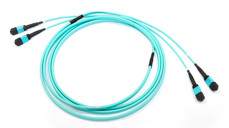
An MTP/MPO trunk cable is terminated on both ends with MTP/MPO connectors (as shown in the following picture). MTP/MPO trunk cables are available with 12, 24, 48 or 72 fibers. These high count MTP/MPO assemblies are ideal for backbone and data center applications that require a high fiber count in a limited space. The plug and play solutions use micro core cable to maximize bend radius and minimize cable weight and size. MTP/MPO trunk cables have several advantages:
- High quality—MTP/MPO trunk cables are factory pre-terminated, tested and packaged along with the test reports. These reports serve as long-term documentation and quality control.
- Decreasing cable volume—MTP/MPO trunk cables have very small diameters, which decrease the cable volume and improve the air-conditioning conditions in data centers.
- Time saving—With the special plug and play design, MTP/MPO trunk cables can be incorporated and immediately plugged in. It greatly helps reduce the installation time. You don’t need to terminate them in the field, which can be a time- and energy-consuming project.
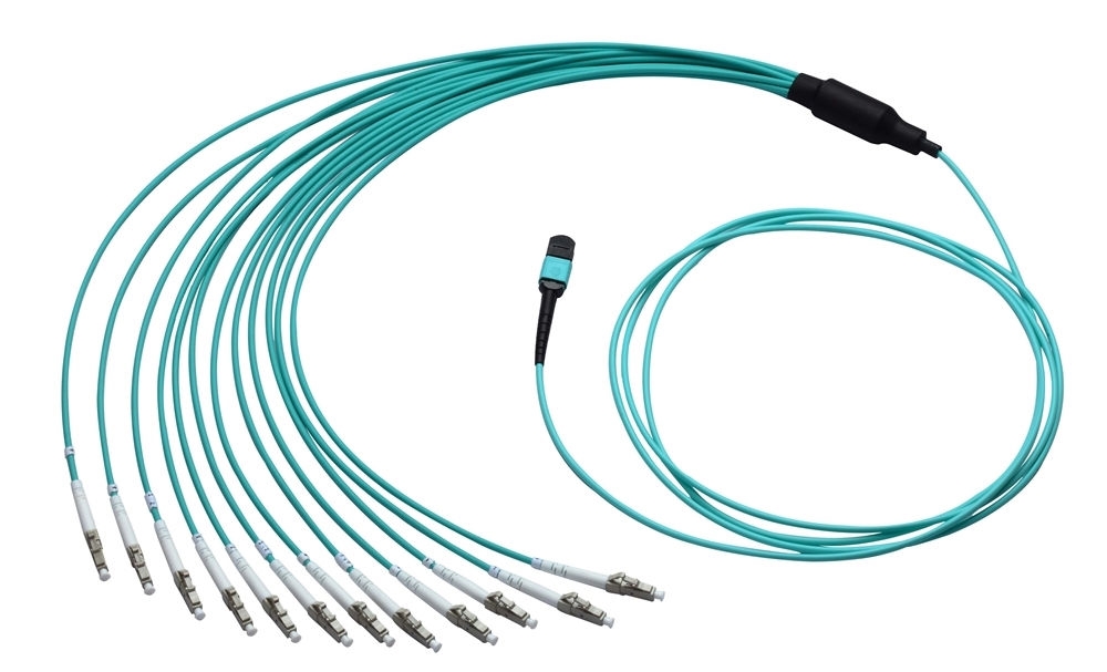
MTP/MPO harness cable (as shown in the following picture) is also called MTP/MPO fan-out cable or MTP/MPO breakout cable. MTP/MPO harness cable has a single MTP connector on one end and on the other end it breaks out into 6 or 12 connectors (LC, SC, ST, etc.). An MTP/MPO breakout cable is available in 4, 6, 8, or 12 fiber ribbon configurations with various length options like 10, 20, or 30 meters and other customized lengths. MTP/MPO fan-out assemblies provide connection to equipment or panels that are terminated with ST, SC, FDDI, or ESCON connectors and meet a variety of fiber cabling requirements. Such assemblies are pre-wired available for patch panels and wall enclosures. They are designed for high density applications with required high performance. Benefits of MTP/MPO harness cable include:
- Space saving—The active equipment and backbone cable is good for saving space.
- Easy deployment—Factory terminated system saves installation and network reconfiguration time.
- Reliability—High standard components are used in the manufacturing process to guarantee the product quality.
MTP/MPO cassettes are designed to reduce installation time and cost for an optical network infrastructure in the premises environment. MTP/MPO cassette modules provide secure transition between MTP/MPO and LC or SC discrete connectors. They are used to interconnect MTP/MPO backbones with LC or SC patching. The modular system allows for rapid deployment of high density data center infrastructure as well as improved troubleshooting and reconfiguration during moves, adds and changes. Advantages of MTP/MPO cassettes are:
- Optimized performance—Low insertion losses and power penalties in tight power budget, high-speed network environments.
- High density—12 or 24 fiber cassettes can be mounted in 1U scaling up to 72 or in 3U scaling up to 336 discrete LC connectors.
- MTP/MPO interface—MTP/MPO components feature superior optical and mechanical properties.
MTP/MPO cables are a good choice for a wide variety of applications. They can be used for backbones, disaster recovery, building fiber optic distribution, quick setup of new wiring hubs, warehouses, direct termination of ribbon cables, repair of plug and play universal system solutions, and parallel optical interconnects between servers.
MTP/MPO solutions are really good choices for your high density data center applications. They are capable of thousands of connections. Fiberstore offers a wide range of MTP/MPO solutions, like MTP/MPO trunk cables, MTP/MPO harness cables and MTP/MPO cassettes. And we also provide various fiber optic patch cables, like polarization maintaining patch cables, and fiber loopback cables, etc. All those cables are pre-terminated and tested to make sure high performance.
Posted by: jowang at
02:58 AM
| No Comments
| Add Comment
Post contains 670 words, total size 6 kb.
April 25, 2016
With the increasing need for faster data transfer rates, 40G networks have been very popular now to provide higher data rates and meet higher application needs. To deploy 40G Ethernet, we need different connectors to achieve network connectivity and different feasible cabling infrastructure. How many cabling options are available? There are several choices for you and they will be discussed in this article.
Active optical cable uses electrical-to-optical conversion on the cable ends to improve speed and distance performance of the cable without sacrificing compatibility with standard electrical interfaces. It is an alternative to optical transceivers, eliminating the separable interface between transceiver module and optical cable. An AOC consists of bend-insensitive multimode or single-mode fiber cable, fiber optic transceivers, control chip and modules. This integrated optical module solution removes the complicated optical fiber interface and can eliminate the separable interface between transceiver module and optical cable. Compaired to direct attach copper cable, AOC weighs less and can support longer transmission distance. However, it costs more than copper cable.
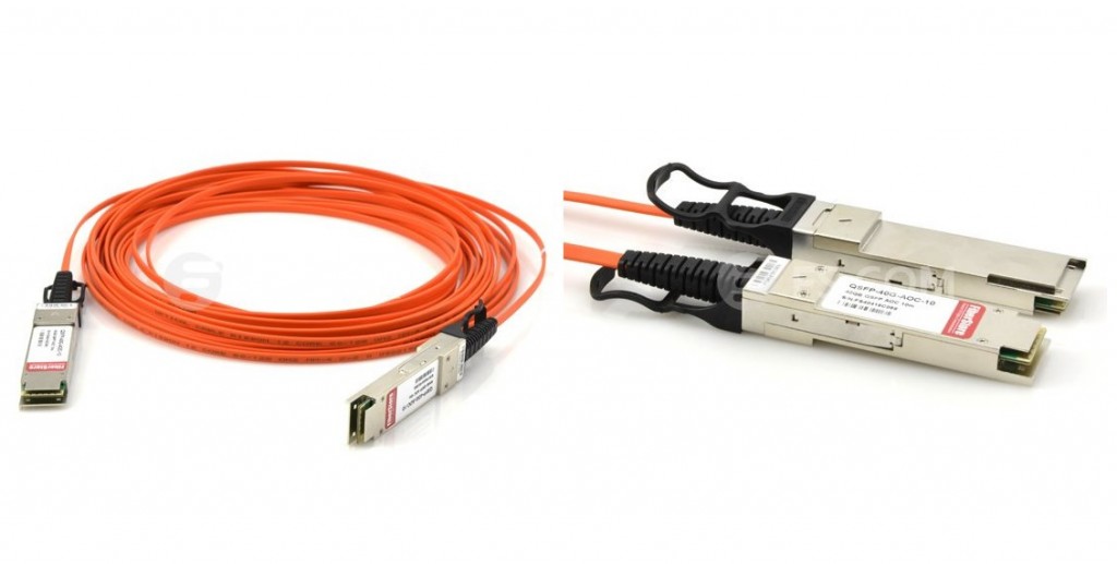
40G active optical cable for 40GbE applications is terminated with a 40GBASE QSFP+ transceiver on one end while on the other end, it can be terminated with QSFP+ connector, SFP+ connector, or LC/SC/FC/ST connector. QSFP+ AOC integrates four data lanes in each direction with 40Gbps aggregate bandwidth. Each lane can operate at 10Gbps with lengths ranging from one to 100m. It is compliant with the QSFP MSA and IEEE P802.3ba. QSFP+ AOC is designed to meet the requirements of high speed, high density and low power consumption for applications in today's data centers via optical fiber cable. The following picture shows a Cisco QSFP-H40G-AOC5M compatible 40G QSFP+ to QSFP+active optical cable.
Except choice of fiber optic cable, copper cable is also a good choice for your 40G applications. Copper cables are specially designed for short-reaches in data center. They are less expensive than fiber cables. There are several twinaxial cables available to support 40G. 40G direct attach copper cable (DAC) includes active DACs and passive DACs. Passive copper cables are prefered alternative for short-reaches in the data center. QSFP+ (quad small form-factor pluggable plus) copper cable assemblies are developed for high-density applications. They offer a cost-effective and low-power option for high speed data center interconnects up to 10 meters.
40GbE passive copper cables provide robust connections for 40G systems and have low power consumption which improves data center power consumption and thermal efficiency, which makes them ideal for 40G LAN, HPC and SAN applications. QSFP+ to QSFP+ passive copper cable and QSFP+ to 4SFP+ passive breakout copper cable are the two common types of QSFP+ cables. The picture below shows a Cisco QSFP-4SFP10G-CU3M compatible 40G QSFP+ to 4SFP+ passive copper cable.
Besides, MTP/MPO fiber cable is also a common option. The IEEE 802.3ba standard specifies MPO (multifiber push-on) connectors for standard-length multimode fiber connectivity. MTP/MPO is the designated interface for multimode 40G. With small, high-density form factor, it is ideal with higher-speed Ethernet equipment. A 12-fiber MPO connector interface can accommodate 40G, which is usually used in 40G data center. The typical implementations of MPO plug-and-play systems split a 12-fiber trunk into six channels that run up to 10 Gigabit Ethernet. 40G system uses 12-fiber trunk to create a Tx/Rx link, dedicating 4 fibers for 10G each of upstream transmit, and 4 fibers for 10G each of downstream receive. The upgrade path for this type of system entails simply replacing the cassette with an MPO-to-MPO adapter module.
40 Gigabit Ethernet has broad applications and is of design flexibility. Migrating to 40 Gigabit Ethernet will prove very cost-effective for those who do it right. As for 40G cabling, MTP/MPO fiber cables and 40G QSFP+ cables are cost-effective options. Fiberstore provides all these kinds of fiber optic cables and copper cables with high quality and competitive price. Moreover, the direct attach cables are tested in practical applications to ensure the superior performance.
Posted by: jowang at
10:21 AM
| No Comments
| Add Comment
Post contains 669 words, total size 6 kb.
April 22, 2016
An increasing number of applications require considerable bandwidth to support the transfer and streaming of large data, video and audio files. To meet the faster rates of data transmission, data carrying techniques have also gone through big technological evolutions. Two commonly used transmission standards, copper and fiber optic cables have progressed a lot to provide the needed bandwidth for data transmission over 10 Gigabit Ethernet applications. In this post, we will talk about these two kinds of cabling solutions for 10 Gigabit Ethernet.
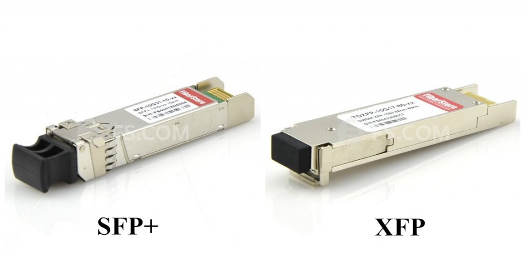
Optical fiber connections are constructed with a combination of fiber optic cables and optical transceivers. The latter receives digital signals from Ethernet devices (switch or adapter card) and then converts them into optical signals so that they can transmit over the fiber. The most widely used optical transceiver for 10 Gigabit Ethernet is the enhanced version of the SFP (small form factor pluggable) transceiver, which is SFP+ transceiver. SFP+ transceiver has the same mechanical characteristics as SFP transceiver. It is capable of supporting 10Gbps data rates. Besides SFP+ transceiver, XFP (10 Gigabit small form factor pluggable) transceiver also can support 10 Gigabit Ethernet. Compared with XFP transceiver, SFP+ transceiver has smaller form factor, allowing for much more dense packaging of ports on switches. The picture below shows a Cisco SFP-10G-LR-S SFP+ transceiver and a Cisco ONS-XC-10G-C XFP transceiver.
How to choose a fiber optic cable fot your 10G applications? It mainly depends on the transmission distance that you need. There are various types of optical transmission. Short range and long range are the two commonly available types. Short range supports connections of up to 300 meters, while long range supports connections of up to 10 kilometers. Multimode fiber cables are typically used for short range transmission and single-mode fiber cables are used for long range transmission.
The final consideration on fiber optic cable is the connector type. The main differences among types of connectors lie in dimensions and methods of mechanical coupling. Multimode fiber cables and single-mode fiber cables require different connectors. SC and LC connectors are the most common types. Note that these cables can be connected to either XFP or SFP+ transceivers. The connector type defines the mechanical specifications of the fiber-to-transceiver interface. Thus, one could have an XFP transceiver on one end of a 10G Ethernet fiber cable and an SFP+ transceiver on the other end. As long as the cable type and connector type match, there is no problem.
For copper cables supporting 1 Gigabit Ethernet, the Category 5 unshielded twisted pair (Cat5-UTP) is utilized. But for 10 Gigabit Ethernet cabling, the standards body determined that even the enhanced Cat5e UTP traditional Ethernet cable would not be able to carry the signal reliably for any significant distance. So a new specification, was introduced and named 10GBASE-T. This calls for a 4-wire twisted pair cable with even more stringent limitations on cross-talk. It is called Cat 6a. 10GBASE-T cables for up to 100 meters are supported with a RJ45 connector on either end. Another copper cabling choice is the 10G SFP+ direct attach copper cable. With SFP+ connectors on both ends, SFP+ direct attach copper cables support 10Gbps Ethernet data transmission. 10G SFP+ direct attach copper cable like HP J9285B (as shown below) supports transmission distance up to 12-15 meters, which is often more than enough for interconnecting systems in racks in data centers.
Copper cabling is popular for transmitting data between devices due to its low cost, easy installation and flexibility. Copper is best when utilized in short lengths, typically 100 meters or less. When employed over long distances, electromagnetic signal characteristics hinder performance. In addition, bundling copper cabling can cause interference, making it difficult to employ as a comprehensive backbone. For these reasons, copper cabling has become the principal data carrying technique for communication among PCs and LANs, but long-distance transmission.
XFP transceivers, SFP+ transceivers, copper cables and fiber optic cables are all the choices for your 10 Gigabit Ethernet connections. They are able to meet your 10Gbps requirements. As a professional manufacturer and suplier in the field of optical network devices, Fiberstore offfers a large variety of high quality SFP+ transceivers, XFP transceivers, fiber optic cables and copper cables with competitive prices for your 10G applications.
Posted by: jowang at
03:31 AM
| No Comments
| Add Comment
Post contains 717 words, total size 6 kb.
April 20, 2016
Today, more bandwidth is needed to support the use of server virtualization, and the amount of data that needs to be transmitted to and from storage area networks (SANs) has also dramatically increased. To accommodate the fast growing number of operating systems and applications and data transmission between servers and switches, SFP+ direct attach cable (DAC), has been a preferable solution for it can provide a lower-power means for operation on short fiber optic links or short copper connections. How much do you know about SFP+ direct attach cable?
First, we need to know what SFP+ direct attach cable is. It is a fixed assembly that is purchased at a given length, with SFP+ connector modules permanently attached to each end of the cable. SFP+ direct attach cable uses an enhanced SFP+ connector to transmit and receive 10Gbps data through one paired transmitters and receivers over a thin twinax cable or a fiber optic cable. It provides high performance in 10 Gigabit Ethernet network applications. 10G SFP+ direct attach cable is designed to use the same port as an optical transceiver, but compared with optical transceivers, the connector modules attached to the cable leave out the expensive optical lasers and other electronic components, thus achieving significant cost savings and power savings in short reach applications.
SFP+ direct attach cable is a low cost, low power consumption and low latency solution that is ideal for high-density, in-rack 10Gbps connections between servers and switches. It provides better cable management for high-density deployments and enhanced electrical characteristics for the most reliable signal transmission. Here are several outstanding advantages of SFP+ direct attach cables.
- MSA compliant—fully conform to the SFP+ MSA specifications
- High speed—support 10 Gbps data rates with backwards compatibility to 1 Gbps
- Reliability—RoHS compliant with excellent EMI performance and high reliability
- Scalability and flexibility—provide enhanced scalability and flexibility, and higher density for today's data centers and storage area networks
- Space saving—offer the smallest 10 gigabit form factor and a small overall cable diameter for higher density and optimized rack space in 10G Ethernet uplinks and Fibre Channel
- Cost saving—cost up to three times less than fiber optic solutions, while offering lower latency and consuming up to 50% less power per port than current copper twisted-pair cabling systems
Generally speaking, SFP+ direct attach cable can be divided into SFP+ direct attach copper cables and SFP+ active optical cables (AOCs). This part will discuss these two kinds of SFP+ direct attach cables.
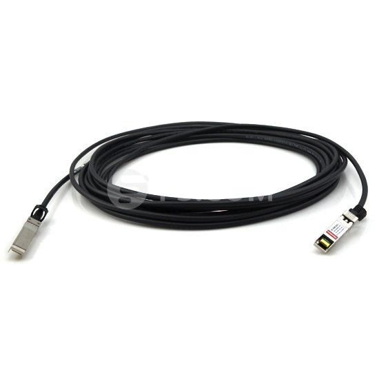
There are two types of SFP+ direct attach copper cables, SFP+ active copper cable (ACC) and SFP+ passive copper cable (PCC). SFP+ passive copper cable (PCC), or passive SFP+ DAC, is fully compliant to the SFF-8431 SFP+ MSA. It has no signal amplification in the cable assembly. When it is utilized, electronic dispersion compensation (EDC) is typically used on the host board designs. EDC allows for an extended length of passive cable assemblies. They deliver high-speed connectivity between active equipment with SFP+ ports. The copper cable trunks are made to order, reducing installation time and maximizing flexibility. The low power consumption assists in making the passive copper cable assembly an economic solution for within rack or rack to rack applications. SFP+ active copper cable (ACC) has signal amplification and equalization in the cable assembly. SFP+ ACC assemblies are typically used in host systems that do not employ EDC. They also incorporate Rx LOS and Tx Disable features. As with passive cables, the industry standard EEPROM signature enables the host system to differentiate between an active copper cable and a fiber optic transceiver. The picture below shows an HP JG081C compatible 10G SFP+ passive direct attach copper cable.
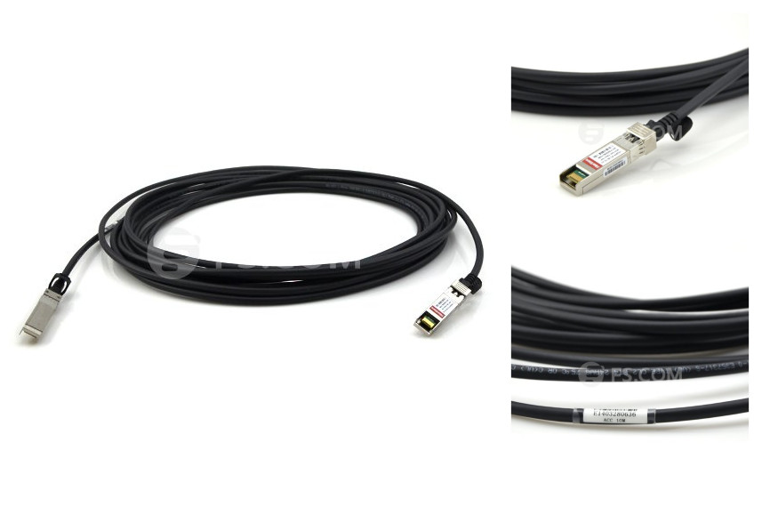
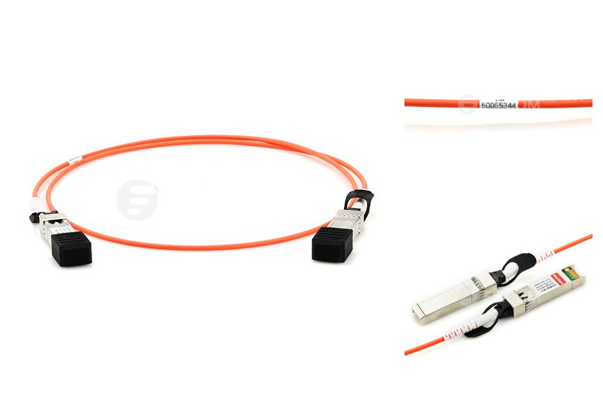
SFP+ active optical cable is composed of SFP+ optical transceivers in both ends and fiber optic cable in between. This integrated optical module solution removes the complicated optical fiber interface and brings friendly electrical-to-electrical interface to users. SFP+ AOC accepts the same electrical inputs as a traditional copper cable. It uses optical fiber and electrical-optical conversion on the cable ends to improve speed and data transmission distance of the cable while not sacrificing compatibility with standard electrical interfaces. SFP+ AOC is designed to meet the requirements of high speed, high density and low power consumption for applications in today’s data centers via optical fiber wire. It has been a preferable interconnect solution for SFP+ applications. SFP+ AOC is compliant to industrial standard SFP MSA and provides high performance SFP+ interfaces, supporting 10Gb/s bi-directional operation. The image below shows a Cisco SFP-10G-AOC10M compatible 10G SFP+ active optical cable.
SFP+ direct attach cable can provide you with a cost-effective and low power consumption solution for your high-density 10 Gigabit applications. It has a lot of advantages. These three kinds of 10G SFP+ direct attach cable assemblies, 10G SFP+ passive copper cable (PCC), 10G SFP+ active copper cable (ACC), and 10G SFP+ active optical cable (AOC) are of their special applications. SFP+ direct attach cable now has been a very popular choice in the market.
Posted by: jowang at
07:26 AM
| No Comments
| Add Comment
Post contains 856 words, total size 7 kb.
April 18, 2016
The rapid growth of global regional and local fiber communication network over the past few decades contributes to a higher demand for cables which can provide lower-power means for high-speed and high-performance connections. Dirrect attach cable (DAC), is a cost effective and proven solution for interconnecting network applications. It can provide inexpensive and reliable connections using either copper cables or fiber cables. What is DAC? Here is what you need to know about DAC.
A direct attach cable is a fixed assembly which is purchased at a given length, with the connector modules permanently attached to each end of the cable. DAC is designed to use the same port as an optical transceiver, but compared with optical transceivers, the connector modules attached to the DAC leave out the expensive optical lasers and other electronic components, thus achieving significant cost savings and power savings in short reach applications.
Direct attach cables can be divided into different types according to different criteria. According to the cables used, direct attach cables include copper cable assemblies and fiber optic cable assemblies. Besides, according to the data rate supported by different connector modules, DAC assemblies can be classified into 10G SFP+ cables, 40G QSFP+ cables, and 120G CXP cables.
Direct attach copper cables can be divided into active and passive versions. In the active direct attach copper cable, there are signal processing electronics in the modules to improve signal quality and provide a longer cable distance. Otherwise, direct attach copper cable is considered passive. However copper cable is heavy and bulky, in order to overcome the disadvantages, active optical cable (AOC) assembly is booming in the market. AOC provides more advantages, such as lighter weight, high performance, low power consumption, low interconnection loss,etc.
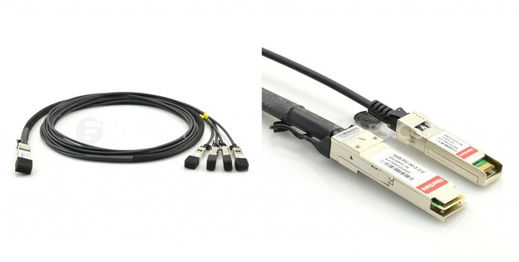
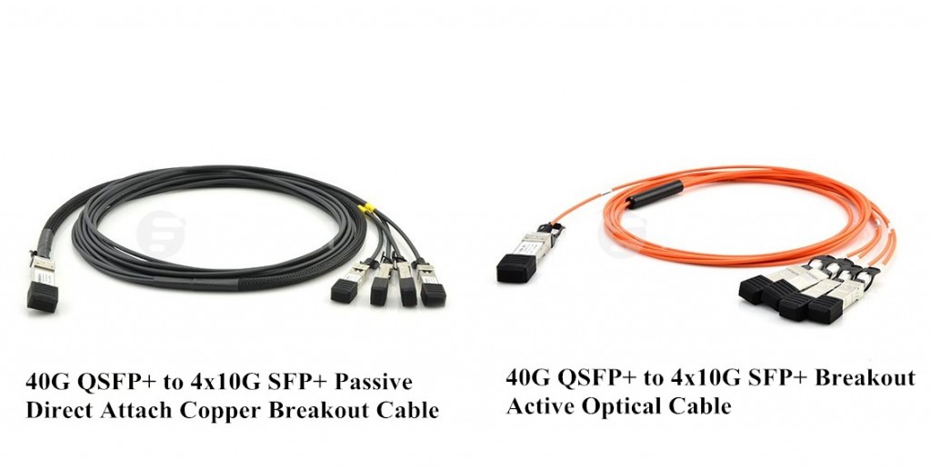
And we can also divide DACs according to the number of connectors on the end of the cable. Most DAC assemblies have one connector on each end of the cable. But there is a special kind of DAC assembly which may have 3 or 4 connectors on one end of the cable. For instance, Cisco QSFP-4SFP10G-CU3M 40G QSFP+ to 4x10G SFP+ passive direct attach copper breakout cable, and Cisco QSFP-4X10G-AOC5M 40G QSFP+ to 4x10G SFP+ breakout active optical cable, as shown in the following picture, they both have a single QSFP+ connector rated for 40Gbps on one end and four SFP+ connectors, each rated for 10Gbps, on the other end.
There are 10G SFP+ cables, 40G QSFP+ cables, 120G CXP cables. Direct attach cable is used to connect one mobility access switch with another when forming a stack. To make sure they can function well, properly installation is needed. This part provides a DAC installation guide, using 40G QSFP+ cables as an example.
To Install or Rremove a 40G QSFP+ to QSFP+ Cable40G QSFP+ to QSFP+ cable has a QSFP+ module on each end of the cable. To install a QSFP+ to QSFP+ cable, first align the QSFP+ transceiver module (with the clasp on top) at one end of the cable with the port in the chassis, and then horizontally and gently push in the module to fully seat it in the port. To remove a QSFP+ to QSFP+ cable, first gently press and release the QSFP+ transceiver module, and then holding the cable, gently pull the clasp on the cable to pull out the transceiver module.
To Install or Remove a 40G QSFP+ to 4x10G SFP+ Cable40G QSFP+ to 4x10G SFP+ cable combines one 40G QSFP+ module on one end and four 10G SFP+ module on the other end. The installation and removal procedures of 40G QSFP+ connector are introdueced above. Here only introduced the installation and removal of 10G SFP+ module. To install an SFP+ transceiver, first align the module with the SFP+ port, with the golden plating facing the spring tab in the SFP+ port. If the chassis has two rows of ports, the spring tab in a port is on the bottom in the upper row and on the top in the lower row. Then slightly press the module against the spring tab so you can push the module straight into the port. To remove an SFP+ transceiver, first press the module with your thumb and then gently pull the clasp on the cable to pull out the transceiver module.
After the installation, remember to verify that the transceiver module or direct attach cable is installed correctly. Fiberstore provides various kinds of high speed interconnect DAC assemblies including 10G SFP+ cables, 40G QSFP+ cables, and 120G CXP cables. All of our direct attach cables can meet high demand to cost-effectively deliver more bandwidth, and can be customized to meet different requirements.
Posted by: jowang at
07:56 AM
| No Comments
| Add Comment
Post contains 790 words, total size 6 kb.
April 15, 2016
With more and more data centers upgrading to 40G and 100G, high density seems to be the trend in optical communication industry. Due to the shrinking of port size and advancement of technology, switches are able to provide more ports and higher data rates. To fit these ports and to achieve photoelectric conversion with higher data rate, fiber optic transceivers also shrink largely in both size and interface. However, high density also brings new problems.
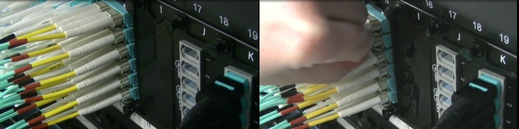
It is inevitable that fiber optic connectors need to be plugged into or pulled out from switches during the cabling process and daily maintenance. For a high density cabling, it becomes much more difficult to get access to each patch cable and connector with your fingers. And it is almost impossible to unplug those connectors on a high density patch panel, especially when they are right in the middle of the patch panel. And also, for fiber patch cords with connectors like LC connector that are locked into the interfaces, it would be even more difficult, because first you have to unlock the connector and then pull it out from the port. High density cabling and maintenance seems to be difficult and time-consuming. To solve these kinds of situations, a special tool comes out, which is push-pull patch cord, or push-pull tab patch cable. Push-pull tab patch cable offers you a simple and easy solution for your high density cable management. And the following text will explain what it is and why you should choose it.
Push-pull tab patch cable is a new patch cord with a special "pull" tab design which can help to solve the problem of finger access in high density cabling. It has the same components and internal structure as traditional patch cords, except a tab attached to the connector used to push in and pull out the whole connector. But this little change can make a big difference. This small push-pull tab looks simple but it is functional and of great importance to high density cabling in 40/100G migration. There are mainly two kinds of push-pull tab patch cables, for high density cabling for 40G/100G usually employs MPO and LC connectors.
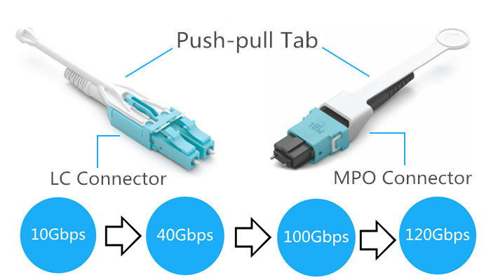
Push-pull Tab LC Patch Cable: The main body of the LC connector is of standard size. The push-pull tab looks simple but it is linked to the latch of the LC connector. When the tab is pulled the latch will be unlocked easily and the LC connector can be easily pulled out from the patch panel. It has been proved that push-pull tab LC cable can increase cabling density greatly.
Push-pull Tab MPO Patch Cable: The tab in an MPO connector can greatly simplify the use of MPO connectivity when manual access to the release slider and rear portion of the connector is restricted. With this tab design, easy insertion and extraction of MPO patch cords can be achieved.
Why choose push-pull tab patch cables? They are chosen for reasons. The benefits of push-pull tab patch cords are not limited to the easy access of the optical connectors. There are other benefits that you can get from them.
- Higher flexibility and adjustability: Push-pull patch cords are available in various specifications, so they can connect devices from 10Gb/s to 100Gbp/s or even more.
- Reliability: Push-pull tab patch cords provide safe and easy push and pull of specific connectors without affecting other connectors around it.
- Space-saving: With push-pull tab patch cords, spare space for cabling is reduced, which can increase the density of cabling further more.
- Economical: High density and ease of installation provide a low initial investment cost. And the benefits above provide a high return on investment.
Push-pull tab patch cords make cabling become much easier. All you need is just your hand. No external tools are required. Push-pull tabs can offer you exceptional finger access in a highly dense environment. Push-pull patch cords can be inserted and removed just by pushing and pulling the connector. And these cables are available with single-mode and OM3, OM4 optical cable types. If you are looking for a connection solution for your high density devices, push-pull tab patch cords, with high durability and flexibility, can be a good a choice.
Posted by: jowang at
02:28 AM
| No Comments
| Add Comment
Post contains 727 words, total size 6 kb.
April 13, 2016
To implement 40G Ethernet network, 40GBASE fiber optic transceivers, a high-performance and flexible component, are developed and widely used. 40GBASE optical transceivers are mainly of two different package forms, which are CFP transceiver (C form-factor pluggable transceiver) and QSFP+ transceiver (quad small form-factor pluggable plus). QSFP+ transceiver is the more commonly used module type in 40G Ethernet networks. This post will mainly discuss how to choose a 40GBASE QSFP+ transceiver. 40GBASE QSFP+ transceivers are used to interface networking hardware to a fiber optic cable, the choice of them depends on many factors, like the media system, the connector type, transmission distance, wavelength, etc. Thus you should consider all these factors comprehensively before you choose them.
First, choose the right QSFP+ transceiver according to the transport media, namely the fiber type. According to the IEEE 802.3ba 40G Ethernet standard, there are three types of transceivers used respectively in three types of transport media: single mode fiber (SMF), multimode fiber (MMF) and copper.
- SMF: 40GBASE-LR4 QSFP+ transceiver reaches 40 Gb/s Ethernet over four wavelengths carried by a singlemode fiber optic cable.
- MMF: 40GBASE-SR4 QSFP+ transceiver reaches 40 Gb/s Ethernet over four short-range multimode fiber optic cables.
- Copper: 40GBASE-CR4 QSFP+ transceiver reaches 40 Gb/s Ethernet over four short-range twinaxial copper cables bundled as a single cable over a standard pair of G.652 single-mode fiber.
Choose the right transceivers which are compliant with the proper connectors. The connectors widely-used mainly have following types: duplex LC connector and MPO connector (or MTP connector, a high-performance MPO connector). For instance, Cisco QSFP-40G-LR4 40GBASE-LR4 QSFP+ transceiver is compliant with the duplex LC connector, while Cisco QSFP-40G-SR4-S 40GBASE-SR4 QSFP+ transceiver and HP JG709A 40GBASE-CSR4 QSFP+ transceiver are compliant with the MPO connector. The picture belows shows duplex LC connector and MPO (MTP) connector.
 connector")
The wavelength that QSFP+ transceivers operate on is another important factor in choosing the proper QSFP+ transceiver. For instance, QSFP-40G-LX4 QSFP+ transceiver converts 4 inputs channels (1271nm, 1291nm,1311nm, 1331nm) of 10Gb/s electrical data to 4 CWDM optical signals, and multiplexes them into a single channel for 40Gb/s optical transmission. While some other QSFP+ transceivers like QSFP-40GBD-SR QSFP+ transceiver consists of two 20-Gbps transmit and receive channels in the 832-918 nm wavelength range.
When choosing the most appropriate QSFP+ transceiver, you also need to consider the transmission distance and the reach requirements you need in reality. The most common types of QSFP+ transceiver divided by its transmission distance can reach up to 100m, 150m, 300m, 400m, 1km, 2km, 10km, 40km, etc. For example, 40GBASE-LR4 QSFP+ transceiver can reach up to 10km, suitable for long reach transmission; 40GBASE-LX4 QSFP+ transceiver is designed to supports link lengths of 100m and 150m respectively on laser-optimized OM3 and OM4 multimode fiber cables. And some others, like 40GBASE-ER4 QSFP+ transceiver which supports link lengths of up to 40km on single-mode fiber cable is designed to use in long distance transmission.
The total cost on QSFP+ transceivers is a large sum of money. Cost is one aspect that should be considered in 40G QSFP+ transceiver selection. To a limit buget, you have to figure out the best choice. Third party transceivers that are compatible with a variety types of switches can be found in today's market. They have the same performances that the original brand transceivers have, but cost less money. Selecting compatible QSFP+ transceivers has become the choice of many data centers, and it is necessary to select them from a company that assures 100% compatibility and interoperability.
To achieve a fast and successful selection of the 40G QSFP+ transceivers, you must first find out what kind of QSFP+ transceiver you need. Whether you need singlemode fiber QSFP+ transceiver or multimode fiber QSFP+ transceiver, duplex LC connector or MPO connector, or to transmit 100m or 10km, you should take all these factors into consideration. Thus you make the best selection for your network.
Posted by: jowang at
02:23 AM
| No Comments
| Add Comment
Post contains 659 words, total size 6 kb.
April 11, 2016
Most optical networks today use components that may come from various suppliers, which makes it particularly important to test the compatibility and interoperability of each fiber optic transceiver in the network. In a network with SFP+ transceivers, verifying the performance of them when they are first deployed is necessary and straightforward. How to test an SFP+ transceiver module to make sure that it can function well? It will be discussed in the following text.
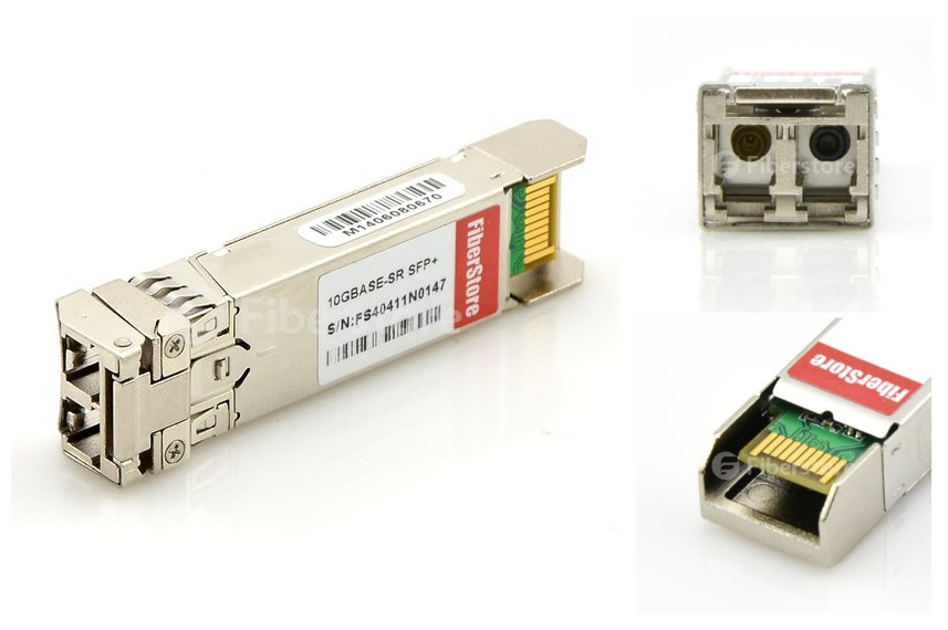
SFP+ is a hot-pluggable multi-rate optical transceiver for data communications and storage-area network (SAN) applications. As SFP+ transceiver becomes more pervasive, engineers need to become more familiar with some of the key challenges linked to testing SFP+ capable devices. We know that basically an SFP+ transceiver consists of a transmitter and a receiver. When a transmitter connects with a receiver through a fiber, the system doesn't achieve your desired bit-error-ratio (BER). Where is the problem? Is it the transmitter or the receiver? Perhaps both are faulty. A low-quality transmitter can be compensated by a low-quality receiver (and vice versa). Thus, specifications should guarantee that any receiver will interoperate with a worst-case transmitter, and any transmitter will provide a signal with sufficient quality such that it will interoperate with a worst-case receiver. The picture below shows a Brocade 10G-SFPP-SR 10GBASE-SR SFP+ transceiver.
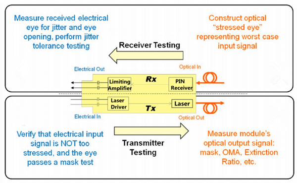
The test of an an SFP+ transceiver module can be divided into two parts: the transmitter testing and the receiver testing.
SFP+ Transmitter TestingSFP+ transmitter parameters may include wavelength and shape of the output waveform. There are two steps to test a transmitter:
1. The input signal used to test the transmitter must be good enough. Measurements of jitter and an eye mask test must be performed to confirm the quality using electrical measurements. An eye mask test is the common method to view the transmitter waveform and provides a wealth of information about overall transmitter performance.
2. The optical output of the transmitter must be tested using several optical quality metrics such as a mask test, OMA (optical modulation amplitude), and Extinction Ratio.
SFP+ Receiver TestingSFP+ receiver may specify tolerance to jitter and bandwidth. To test a receiver, there are also two steps:
1. Unlike testing the transmitter, where one must ensure that the input signal is of good enough quality, testing the receiver involves sending in a signal that is of poor enough quality. To do this, a stressed eye representing the worst case signal shall be created. This is an optical signal, and must be calibrated using jitter and optical power measurements.
2. Then, testing the electrical output of the receiver must be performed, which includes three basic categories of tests:
- A mask test, which ensures a large enough eye opening. The mask test is usually accompanied by a BER (bit error ratio) depth.
- Jitter budget test, which tests for the amount of certain types of jitter.
- Jitter tracking and tolerance, which tests the ability of the internal clock recovery circuit to track jitter within its loop bandwidth.
During the process of SFP+ transceiver testing, there are several challenges that you need to pay attention to. One challenge is moving seamlessly from a compliance environment to a debug environment. If a measurement fails, how can the designer determine which component is causing the failure and debug the issue to arrive at the root cause? Another problem that most designers face today relates to connectivity: how to get the signal out from the device under test (DUT) to an oscilloscope. Yet another challenge is the increased port density and the testing time required with 48 or more ports per rack.
An SFP+ transceiver' performance is very critical to a whole nework, so it is an indispensable step to ensure its performance. Both transmitter test and receiver test are needed. Fiberstore provides all kinds of compatible SFP+ transceivers branded by Cisco, HP, Arista, Brocade, etc., like Avago AFBR-709SMZ compatible SFP+ module. Every SFP+ transceiver from Fiberstore has been tested carefully to guarantee superior quality.
Posted by: jowang at
09:08 AM
| No Comments
| Add Comment
Post contains 680 words, total size 6 kb.
April 06, 2016
While installing fiber optic cables, you will come across such questions. Should I choose to field terminate fiber optic cables or just turn to pre-terminated fiber optic cables? Which choice is better for the installation? Before jumping to a decision, you need to take a few things into consideration. In this article, we will discuss what cable construction type you need and understand why a pre-terminated fiber option is a better choice for you.
Pre-terminated cabling systems have been in use for a number of years. Nowadays they have been regarded as the "norm" for Data Center applications. There are reasons for it.

Time saving: Without doubt, pre-terminated fiber cables can help you save a lot of time. As the products are terminated in a factory environment and delivered to site, minimal engineering or assembly work is required on site. Pre-terminated solutions also save testing time. The pre-terminated solutions can be tested at the factory and transported to site, which minimises the occurrence of faulty connections.
Space Saving: Pre-terminated fiber cable is much higher in density. And, installers need space to store the components and work areas to make terminations. Using a pre-terminated solution can be space saving as the pre-terminated links are "made to measure" and they don't need to be stored when delivered as needed and can be put to use immediately.
Pre-terminated cables or fiber optic patch cables assemblies eliminate time-consuming field-termination processes and provide a factory-tested and certified endface. But they also have disadvantages. Prepolished connectorized fibers can cost much more than epoxy-style field-polish connectors. And cable length needs to be precisely measured. If pre-terminated cables are too short, you will have to install a replacement; if they are too long, you will have to deal with installation issues associated with managing the extra cable length, which will also cause additional expense.
As you know, optical fiber, mainly made of glass, is very fragile and difficult to install. Termination of installing optical fiber cables has always been perceived as a difficult, expensive, and time-consuming process, whether the termination is done in the field or it is an in-house operation, which discourags a lot of installers. And now, with the development of new high speed systems, termination is becoming more and more difficult. For example, multi-mode fiber networks for 40Gbit/s and 100Gbit/s applications use parallel transmission with 8 or 20 fibers per link utilizing 12-fiber MTP/MPO connectors, making it harder to terminate than a single fiber connector. Instead, a pre-terminated MPO cable would be much easier. Why not choose to field terminate fiber optic cabling systems? Here are several troubles that a field termination may bring to you.

Polishing process: Polishing the fiber is one of the most critical step in the connectorization process. Polishing is the process of creating a smooth surface by rubbing it or using a chemical action, leaving a surface with a significant specular reflection. Polishing finalizes the connector endface and cleans the surface, which has a direct impact on such optical performance parameters as insertion loss, return loss, and bit-error-rate for overall network performance. Reliable polishing processes rely on proper training and a well-equipped termination toolkit. Many installers fear connectorizing optical fiber cable, mainly due to the delicate techniques of polishing.
Connector protection: Another problem is how to protect the connectors. We know that optical fiber connector is a high-precision device with tolerances on the order of microns, it is crucial that the fiber should not only be formed perfectly to align with a mating connector, but that it should be free of any dust or dirt. Failing to do so can cause high insertion loss and high reflection, and can contaminate the equipment to which the connectors and patch cords will be connected. In a field termination process, extra attention must be paid to the handling of the collectors. Bad environment may increase the possibility of a connector failure.
Cost: Besides, fiber termination involves a heavy investment into the proper tools and test equipment to make a proper fiber connection at the location. For example, you need a cable stripper to remove the tight buffer, a ruler and a marker to measure the length and mark on the fiber jacket, and some fiber optic cleaning fluid to clean the bare fiber, and so on. The most costly part of field termination kit is going to be your cleaver. Some only cleave multimode fibers and some do both multimode and singlemode fibers. So if you decide to field terminate fiber optic cables, you must prepare all those termination tools that you need, which is a big load for field termination.
Pre-terminated fiber cable is relatively a much easier way to install fiber cable. The connectors you specify are pre-terminated for you, and the fiber cable you specify is cut to the proper length that you need. When the installation is over, you can just plug and play fiber optic system. It is perfect for beginners and also convenient for professional fiber optic installers. Many cable and patchcord manufacturers offer a cable termination service. If you have a good cable plant layout design and can accurately calculate cable lengths between termination points, all you have to do is specify what kind and number of fibers, the fiber types and connector types and the cable length that you need. Then the manufacturer would supply a completed assembly, and the cable is terminated with connectors, fully tested and fitted with protective sleeving at each end. Pre-terminated fiber cable is an excellent choice.
Pre-terminated fiber cables do offer a number of advantages for a variety of different network installations for reasons of time saving and space saving. However, it doesn't mean that you can get all the benefits offered by a pre-terminated solution. A large amount of planning needs to be carried out prior to installation. Attention to details in the site survey process is critical, or these benefits will be lost and additional cost incurred. A pre-terminated solution is a pre-planned solution. Only when you preplan it well can it work well.
Posted by: jowang at
08:27 AM
| No Comments
| Add Comment
Post contains 1036 words, total size 8 kb.
April 05, 2016
Contaminated fiber optic connectors can often lead to degraded performance and costly failures. To ensure proper performance and reliability, thorough care must be taken to ensure the installation and maintenance of those fiber connectors terminated with fiber optic patch cables and fiber optic pigtails. A properly maintained and cleaned fiber optic cable will help reduce contaminant transfer to an optical interface. How to clean a fiber optic connection? In this post, a brief cleaning guide for fiber optic connections will be given.
To better understand how to clean a fiber optic connection, it is necessary to know some basic information about contamination. Fiber optic cable contamination comes in various ways. There are two common forms of contamination: dust and oils. Without noticing, oils from your fingers will leave a defect on the fiber noticeable under a fiber scope. And oils also tend to trap dust against the fiber, which can result in scratches on both the fiber connector and the fiber optic it is mated to. Simply removing and re-inserting a fiber has the possibility of contaminating the end of the connector in a facility that may have a higher level of dust. Fiber caps used to prevent fiber ends from being scratched, will collect dirt, oil and dust, and then transfer those contaminants to the fiber when used. So cap ends should be cleaned before inserting them into an interface. It is also important to note that a new cable does not guarantee a clean cable. Any contamination in the fiber connection can cause failure of the component or even the whole system. It is very important that every fiber connector should be inspected and cleaned prior to mating. Cleaning fiber optic components is a requirement for quality connections between fiber optic equipment.

Cleaning fiber optic equipment is one of the most basic and important procedures for the maintenance of fiber optic systems. The general cleaning process includes:
- Make sure that the lasers are turned off before you begin the inspection.
- Remove the protective endcap and store it in a small resealable container.
- Inspect the fiber connector, component, or bulkhead with a fiberscope.
- If the connector is dirty, clean it with a dry cleaning technique.
- Inspect the connector. If the connector is still dirty, repeat the dry cleaning technique.
- Inspect the connector. If the connector is still dirty, clean it with a wet cleaning technique followed immediately with a dry clean in order to ensure no residue is left on the endface. Note: Wet cleaning is not recommended for bulkheads and receptacles, for damage to equipment can occur.
- Inspect the connector again. If the contaminate still cannot be removed, repeat the cleaning procedure until the endface is clean.
During the process of cleaning a fiber optic connector or other qu, several things need to keep in mind. Read the reminders and warnings before you begin this process. Make sure that the lasers are turned off before you begin the inspection. Invisible laser radiation might be emitted from disconnected fibers or connectors. Do not stare into beams or view directly with optical instruments. Do not scrub the fiber against the fabric or clean over the same surface more than once. This can potentially contaminate or damage your connector. Throw away any used cleaning material, either cards or material cartridges, after use. Be careful not to contaminate the cleaning area of the wipe with your hands or on a surface during folding. Do not scrub the fiber against the wipe. If you do it, it can cause scratches and more contamination. Never use alcohol or wet cleaning without a way to ensure that it does not leave residue on the endface. Improper cleaning can also cause damage to the equipment.
Fiber optic connection cleaning process is a very necessary and critical process. The end of a fiber optic cable and the inner surface of an optical module lens constitute optical surfaces that should be properly cleaned and maintained to ensure optimum reliability and system performance. It is not just important to have the proper tools for the job, but also know when to use them and how to use them.
Posted by: jowang at
06:54 AM
| No Comments
| Add Comment
Post contains 705 words, total size 5 kb.
April 01, 2016
Fiber optic loopback is designed to provide a media of return patch for a fiber optic signal. It is abosolutely an economical solution for a number of fiber optic test applications. Typically used for fiber optic testing applications or network restorations, the loopback signal is used for diagnosing a problem. How much do you know about fiber optic loopback? In this post, some basic infomation about fiber optic loopback will be given.
Fiber optic loopback cable and fiber optic loopback module, are collectively known as fiber optic loopback. Fiber optic loopback is designed to provide a media of return patch for a fiber optic signal, offer a generous yet manageable fiber loop virtually eliminating bend loss, and commonly used for fiber optic testing applications or network restorations. It is used to diagnose the problems of optical networking equipment. Sending a loopback test to network equipment, one at a time, is a technique for isolating a problem. Fiber optic loopbacks are with compact design, and they are compliant with Fast Ethernet, Fibre Channel, ATM and Gigabit Ethernet etc. The picture below shows a fiber optic loopback cable and a fiber optic loopback module.

Fiber optic loopbacks can be with various jacket types, cable diameters, connector terminations and cable lengths. Traditional fiber optic loopbacks (fiber optic loopback cables) can be regarded to be two fiber optic connectors on the same piece of simplex fiber optic patch cable put together, thus it forms a loop. Classified by the connector types, two most commonly used fiber optic loopback cables are SC fiber optic loopback and LC fiber optic loopback, while there are also FC, MTRJ, and MTP types.
Besides the traditional fiber optic loopbacks, there are also molded fiber optic loopbacks (or fiber optic loopback plugs), i.e. fiber optic loopback modules. Unlike the traditional fiber optic loopback cables with visible cable parts, fiber optic loopback module has its cables and fibers well protected inside the housing. It integrates every part into one single body, which help save space and make it easier to operate as well as offer better protection to the whole product. By incorporating a rigid connector shell for fiber protection with an easy to use, ergonomic package, the fiber optic loopback module is designed for durability and performance. Molded fiber optic loopbacks are also mainly available in SC and LC types, which are easy to use for fiber optic test purpose in the lab experiments or manufacturing environment.
A typical application of fiber optic loopback is to check fiber optic transceiver by loopback test. Loopback test is the easiest way to ensure the transceiver is working faultlessly. On fiber optic transceiver manufacturing floors and in R&D labs, a fiber optic loopback is used to verify the transceiver whether it is working perfectly as designed. Basically what the loopback does is directly routing the laser signal from the transmitter port back to the receiver port. Then the transmitted pattern is compared with the received pattern to make sure they are identical and have no error. Loopback test means a hardware or software method, a loopback test, feeds a received signal or data back to the sender. It is utilized as an aid in debugging physical connection problems.
Similar as fiber jumpers, fiber optic loopback can be with various jacket types and cable diameters, and they can be with different terminations and length. Fiberstore makes the fiber optic loopbacks strictly according to industry standard, each of the cable is functionally tested before shipping, and we offer custom assemblies for fiber optic loopbacks such as custom connector configurations and special polished.
Posted by: jowang at
03:05 AM
| No Comments
| Add Comment
Post contains 606 words, total size 5 kb.
32 queries taking 0.1767 seconds, 88 records returned.
Powered by Minx 1.1.6c-pink.

