


May 30, 2016
As we know, fiber optic connectors are used at both ends of a fiber jumper to achieve cross connections of fibers. There are many types of connectors developed for fiber optic jumper cables. For example, single-mode networks have used FC or SC connectors in about the same proportion as ST and SC in multi-mode installations. To choose a proper fiber optic patch cable, fiber optic connector is a very important factor to consider. LC connector is a common connector type used in fiber optic jumper cables. An LC to LC fiber patch cable is a patch cable terminated at both ends with LC connectors. The following text gives a detailed introduction of LC to LC fiber patch cables.
To better understand LC to LC fiber patch cable, you need to have a basic understanding of LC connector first. LC (Lucent Connector) was first developed by Lucent Technologies as a response to the need by their primary customers for a small and low insertion loss connector. Then the LC design was standardized in EIA/TIA-604-10 and is offered by other manufacturers. The ferrule size of an LC connector is 1.25 mm, half the size of SC connector ferrule. LC connector is rated for 500 mating cycles and its typical insertion loss is 0.25 dB. There are solid reasons that LC connector is a preferred connector type for high-performance network. LC connector has a small size, it borrows split-sleeve construction and a cylindrical ferrule (usually ceramic) from SC connector, and it can have a push-and-latch design providing pull-proof stability in system rack mounts.
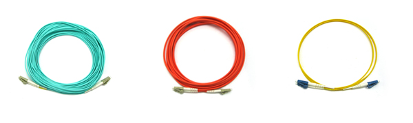
There are many options of LC patch cord. The picture below shows LC to LC fiber patch cables.
- Simplex, duplex or multi-fiber assemblies
- PC, UPC, and APC polish types
- Custom fiber optic cable lengths and jacket colors.
- 0.9mm, 1.8mm, 2.0mm, and 3.0mm outer diameter cables
- Jacket types: Riser, PVC, Plenum rated, or LSZH, all RoHS compliant
- Various fiber types and wavelengths, typical 9/125 single-mode fiber (SMF), 50/125 and 62.5/125 multi-mode fiber (MMF)
Armored LC-LC Patch Cable: Armored fiber optic patch cables retain all features of standard fiber patch cords, but are much stronger. Armored fiber optic patch cables will not get damaged even if stepped by an adult and are rodent-resistant. Armored fiber optic cables are actually as flexible as standard fiber optic patch cords. They are made a with similar outer diameter to standard patch cords, making them space saving and strong. And they can be made with different jacket colors and jacket types, and with LC, SC, FC, ST, LC/APC, SC/APC, FC/APC and other types of connectors.
Multi-Core LC-LC Patch Cable: Multi core fiber patch cord are individually reinforced fibers terminated with fiber optic connectors. 2-288 cores are optional and the sub-branch can be 0.9mm and 2.0mm. Multi-core patch cables are widely used for CATV, LANs, Video, active device termination, telecommunication networks etc. They are now RoHS and REACH certified. There are various connectors like LC, SC, SC/APC, FC, FC/APC, ST available.
Mode-Conditioning LC-LC Patch Cable: Mode-conditioning patch cables are used in 1300nm or 1310nm optical wavelength window, and should not be used for 850nm short wavelength window such as 1000BASE-SX. They are made to allow Gigabit 1000BASE-LX single-mode equipment, such as routers and switches, to be used on existing 62.5µm or 50µm multimode cable plants. There are various connectors available, like LC, SC, SC/APC, FC, FC/APC, ST.
There are many types of LC to LC fiber patch cables, including single-mode and multi-mode types, in simplex and duplex versions. These LC patch cords (with UPC or APC polish type) feature various cable jacket types (Riser or Plenum rated, LSZH or PVC, all RoHS compliant). Fiberstore provides all those kinds of LC to LC patch cables. They are fully tested to guarantee top performance. Each assembly is serialized for easy identification and sealed in individual Ziploc bags. Test results are included in each order. They are constructed with high-quality fiberglass and high-grade connectors for high durability and accuracy.
Posted by: jowang at
06:59 AM
| No Comments
| Add Comment
Post contains 682 words, total size 5 kb.
May 27, 2016
In the market of fiber optic products, there are many kinds of optical transceiver modules, such as GBIC, SFP, SFP+, QSFP+, QSFP28, CFP, and so on. All these transceiver modules provide you with a large variety of options. Which one to choose? For example, will you choose an SFP optical transceiver over a GBIC? Many people are confused about them. It seems that you should first figure out what you need and then know the differences between them before making a decision.
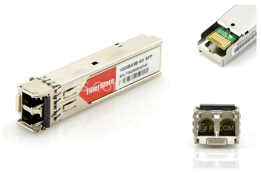
Small form-factor pluggable (SFP) is a specification for a new generation of optical modular transceivers. The devices are designed for use with small form factor (SFF) connectors, and offer high speed and physical compactness. SFP transceivers are expected to perform at data speeds of up to five gigabits per second (5 Gbps), and possibly higher. There are many differernt types of SFP transceivers, and they work with different wavelengths at a designated location or distance. For example, a TRENDnet TEG-MGBSX compatible 1000BASE-SX SFP transceiver, as shown below, uses 850nm for a maximum of 550 meters.
SFP modules are hot-swappable. They can be easily interchanged, electro-optical or fiber optic networks can be upgraded and maintained more conveniently than has been the case with traditional soldered-in modules. Rather than replacing an entire circuit board containing several soldered-in modules, a single module can be removed and replaced for repair or upgrading. The form factor and electrical interface are specified by a multi-source agreement (MSA). SFP is also known as a Mini GBIC as its function is somewhat similar to GBIC transceiver while SFP is smaller in size. SFP transceivers are designed to support SONET, Gigabit Ethernet, Fibre Channel, and other communications standards. Due to its smaller size, SFP is now more and more widely used for both telecommunication and data communications applications.
A gigabit interface converter (GBIC) is a transceiver that converts electric currents to optical signals, and optical signals to digital electric currents. It is a hot-swappable input/output device (it can be removed and replaced without turning off the system) that plugs into a Gigabit Ethernet port or slot, linking the port with the network. Generally, GBIC is with SC connector. It is commonly employed in fiber optic and Ethernet systems as an interface for high-speed networking. The data transfer rate is one gigabit per second (1 Gbps) or more. GBIC modules allow technicians to easily configure and upgrade electro-optical communications networks. A GBIC module is economical, because it eliminates the necessity for replacing entire boards at the system level. Upgrading can be done with any number of units at a time, from an individual module to all the modules in a system.
Based on the definitions of GBIC and SFP, you may have a further understanding on both of them. Is SFP a better choice over GBIC? I think the answer is yes. SFP transceiver is smaller than GBIC module. The difference in size is very desirable for many people, especially for those who deal with lots of them, because it will take up a lot less space. Considering that space in a server location is quite limited, using SFP modules lets you put more within one rack unit than if you used GBICs. Because of this single difference, SFP optical transceivers rapidly gain popularity with administrators who want to maximize their space.
Other basic functions of SFP is almost the same with the GBIC and they are equal in performance. The characteristics of the two, whether for electrical or for fiber optics, are just about identical. So switching from one to the other will not really help your network perform better or make it worse. Though there are some users still using GBICs as their old divice which can not be updated to support SFP, GBIC will gradually be obsoleted and replaced by SFP. So it is a better choice to go with SFP.
SFP transceiver module gains more and more popularity among consumers, and it has replaced GBIC to some extent. Fiberstore can offer those GBIC and SFP transceivers with same performances at more reasonable prices.
Posted by: jowang at
03:11 AM
| No Comments
| Add Comment
Post contains 702 words, total size 5 kb.
May 25, 2016
Many servers in data center can support 40G Ethernet transmissions now. 40Gb QSFP+ is considered to be an economical solution for 40G transmission in data center. And to make them run normally and effectively, fiber patch cables must be used to connect those QSFP+ transceivers plugged in Ethernet switches, as shown in the following picture. As the structure of a 40G transmission is more complex, the selection of fiber patch cords for 40G QSFP+ optics becomes more difficult. This article focuses on how to select proper fiber jumpers for 40G QSFP+ transceivers.
Before jumping to a conclusion, numerous things need to be taken into consideration when selecting a fiber patch cable for a 40G QSFP+ transceiver in practical cabling. In this article, three factors are introduced: the cable type of fiber patch cords, the connector type of fiber patch cords, and ports of switches that need to be connected.
The first factor to consider is the cable type. Optical signals with the same wavelength perform differently when they run through different types of cables. For example, can a 40GBASE QSFP+ transceiver working on wavelength of 850nm be used with OM1 fiber patch cords? Usually, signals with wavelength of 850nm are transmitted over short distance. Thus selecting a multimode fiber patch cord will be more economical. OM1 fiber patch cables are ususally suggested for 100Mb/s and 1000Mb/s networks, and cannot support 40G transmission, because the transmission distance reduces as the data rate raises. OM3 fiber patch cables and OM4 fiber patch cables, these two types of optimized multimode fiber optic cables, are recommended for your 40G transmissions over short distance. And for long distance transmission, you can choose single-mode fiber patch cables.
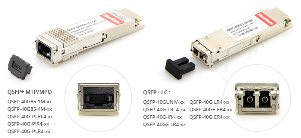
The second factor to consider is what types of connectors are attached on both ends of fiber patch cords. Connector types are usually decided by the interfaces of 40G optical transceivers. Usually, 40G QSFP+ transceivers for short distance are armed with MPO interfaces, and for long distance transmission usually employ LC interfaces. For example, Avago AFBR-79E3PZ compatible 40GBASE-SR4 QSFP+ transceiver has MTP/MPO interface, and can support up to 400m over OM4 MMF. However, there are also exceptions. 40G QSFP+ transceivers like 40GBASE-PLR4 QSFP+ transceiver and 40GBASE-PLRL4 QSFP+ transceiver, they are with MPO interfaces but they can support transmission over long distance. One characteristic of MPO connector is high density which can perfectly satisfy the requirements of 40G transmission. But this kind of connection makes the polarity complex. So when selecting this kind of fiber patch cord, it is very necessary to take the polarity into consideration. The picture below shows 40G QSFP+ transceivers with MPO interfaces and LC interfaces.
The third factor is ports of switches that need to be connected. During practical cabling, two situations are common. One is 40G QSFP+ to 40G QSFP+ cabling and the other is 40G QSFP+ to 10G SFP+ cabling. For 40G QSFP+ to 40G QSFP+ cabling: 40GBASE-SR4 QSFP+ transceiver can be used with OM3 fiber patch cable with MPO interfaces to support up to 100m, and with OM4 fiber patch cable with MPO interfaces to support up to 150m; 40GBASE-LR4 QSFP+ transceiver can be used with single-mode fiber patch cables with LC connectors to support up to 10km. For 40G QSFP+ to 10G SFP+ cabling, fan out patch cable with MPO connectors on one end and four LC duplex connectors on the other end is suggested.
When choosing a fiber patch cord for a 40G QSFP+ transceiver, you need to consider these three factors, the cable type, the connector type and the switch ports. You have to figure out first whether you need single-mode fiber patch cords or multi-mode fiber patch cords, MPO connectors or LC connectors, or QSFP+ to QSFP+ cabling or QSFP+ to 4SFP+ cabling. Fiberstore can provide you with professional one-stop service including the cost-effective and reliable network designing and 40G products.
Posted by: jowang at
02:24 AM
| No Comments
| Add Comment
Post contains 658 words, total size 5 kb.
May 23, 2016
With rapid development of technologies, 100G Ethernet now has become more and more closer to us. Plug-and-play and hot-swappable optical transceivers play an important role in achieving realiable and effective 100G Ethernet. There are several optical transceiver options for 100G Ethernet networks, such as CFP, CXP and QSFP28. Among them, how much do you know about CFP and CXP? Do you know the difference between CFP and CXP? Is CXP transceiver designed to replace CFP transceiver? Today, this post will help you understand these two kinds of 100G optical transceivers.
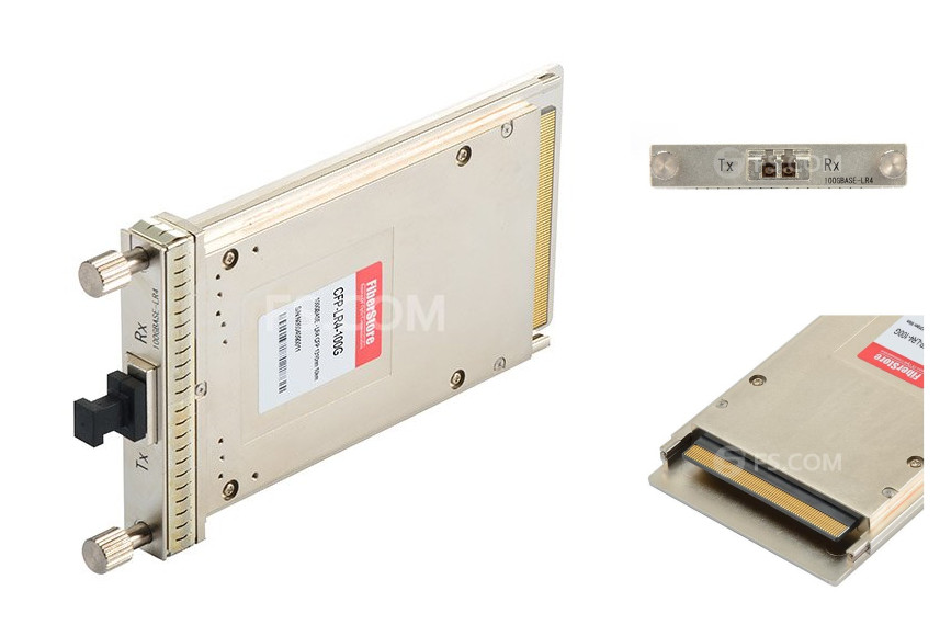
CFP (C form-factor pluggable) is a multi-source agreement (MSA) to produce a common form-factor for the transmission of high-speed digital signals. "C" stands for the Latin letter C, which is used to express number 100 (centum). CFP transceiver also supports 40GbE. The CFP MSA was formally launched at OFC/NFOEC 2009 in March by founding members Finisar, Opnext, and Sumitomo/ExceLight. CFP form factor supports both single-mode and multi-mode fiber and a variety of data rates, protocols, and link lengths, including all physical media-dependent (PMD) interfaces in the IEEE 802.3ba standard. For 40GbE, target optical interfaces include the 40GBASE-SR4 for 100 m and the 40GBASE-LR4 for 10 km. There are three PMDs for 100GbE: 100GBASE-SR10 for 100 m, 100GBASE-LR4 for 10 km, and 100GBASE-ER4 for 40 km. The picture below shows a Juniper Networks CFP-GEN2-100GBASE-LR4 compatible 100GBASE-LR4 CFP transceiver.
CFP was designed after the small form-factor pluggable transceiver (SFP) interface, but is significantly larger to support 100Gbps. The electrical connection of a CFP uses 10×10Gbps lanes in each direction (Rx, Tx). The optical connection can support both 10×10Gbps and 4×25Gbps variants. CFP transceivers can support a single 100Gbps signal like 100GE or OTU4 or one or more 40Gbps signals like 40GE, OTU3, or STM-256/OC-768. The CFP-MSA Committee has defined three form factors:
- CFP—Currently at standard revision 1.4 and is widely available in the market.
- CFP2—Half the size of a CFP transceiver, and is available in the market.
- CFP4—Half the size of a CFP2 transceiver, and the standard is not yet available.
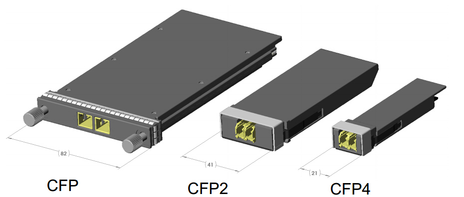
The original CFP specification was proposed at a time when 10Gbps signals were far more achievable than 25Gbps signals. As such to achieve 100Gbps line rate, the most affordable solution was based on 10 lanes of 10Gbps. However improvements in technology has allowed higher performance and higher density, contributing to the development of the CFP2 and CFP4 specifications. Note that CFP, CFP2 and CFP4 modules are not interchangable (but interoperable at the optical interface with approriate connectors).
CXP transceiver is targeted at the clustering and high-speed computing markets, so it is usually called high-density CXP. Technically, CFP transceiver will work with multimode fiber for short-reach applications, but it is not really optimized in size for the multimode fiber market, most notably because the multimode fiber market requires high faceplate density. CXP transceiver was created to satisfy high-density requirements of data centers, targeting parallel interconnections for 12×QDR InfiniBand (120 Gbps), 100 GbE, and proprietary links between systems collocated in the same facility. A CXP transceiver is about 45 mm in length and 27 mm in width, making it slightly larger than an XFP transceiver. It includes 12 transmit and 12 receive channels in its compact package, which is achieved by a connector configuration similar to that of a CFP transceiver. Besides, a CXP transceiver enables a front panel density that is greater than that of an SFP+ running at 10 Gbps. Typical applications of CXP transceivers in the data center include 100GE over copper and 100GE over multimode fiber.
Despite having a similar acronym and emerging at roughly the same time, CFP and CXP form factors are markedly different in terms of size, density, and intended applications. Both CFP and CXP optical transceivers are hot-pluggable, and feature transmit and receive functions, and both support data rates of 40 and 100 Gbps. For 40 GbE and 100 GbE applications, CFP transceiver supports both single-mode and multi-mode fiber and can accommodate a host of data rates, protocols, and link lengths. CXP transceiver is targeted at the clustering and high-speed computing markets. These two types of transceiver modules are complementary, not competitive, according to several sources. The existence of CXP transceiver does not mean the replacement of CFP transceiver.
CFP transceiver and CXP transceiver have both similarties and differences. Which one to choose for your applications? It depends. If you need to build a box that can adapt to any interface, you would probably use CFP transceiver modules. If it's a box that is just focused on the short-reach market, then CXP transceiver modules would be preferable options.
Posted by: jowang at
04:32 AM
| No Comments
| Add Comment
Post contains 779 words, total size 6 kb.
May 20, 2016
10G connections in telecommunication networks have gradually moved from backbones to layer 2 and layer 3. Both the technology and the market of 10G optics are very mature now. 10G modules have advanced from XENPAK transceiver, the first generation of 10G transceiver, to SFP+ transceiver, which is now the most popular 10G transceiver module. Besides, the price of 10G transceiver modules is getting lower, making them become more affordable. This article offers some basic information about 10G SFP+ optics and their connection instructions.
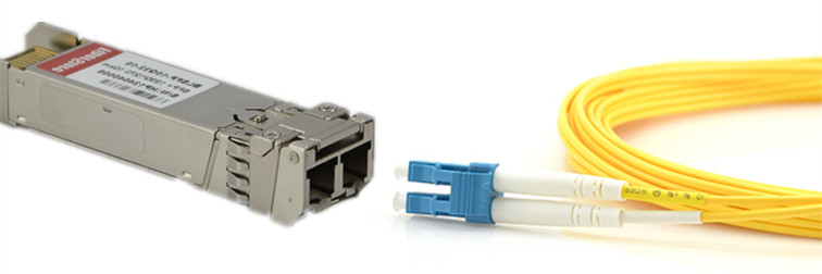
10G SFP+ transceiver has the same form factor of Gigabit SFP optical transceiver. Many SFP+ transceiver modules can support both 1G and 10G data rates to increase their flexibility during practical using. An SFP+ transceiver module usually has two LC ports (as shown in the following picture). A 10G BiDi SFP+ transceiver, which transmits and receives signals using the same fiber optic cable, has only one LC port.
Other than fiber optic transceivers, there are various factory-terminated copper cables and fiber optic cables that are terminated with an SFP+ module on each end of the cable. There are mainly three types of 10G SFP+ cables: 10G SFP+ passive direct attach copper cable, such as HP J9281B compatible SFP+ passive direct attach copper cable, or HP JG081C compatible 10G SFP+ passive direct attach copper cable, 10G active direct attach copper cable and 10G SFP+ active optical cable, such as Cisco SFP-10G-AOC10M compatible 10G SFP+ active optical cable. These 10G SFP+ cables eliminate the use of additional patch cables and can be directly plugged into SFP+ ports on switches. It is acceptable that these SFP+ cables are cost-effective and reliable solutions for 10G connections over short distances.
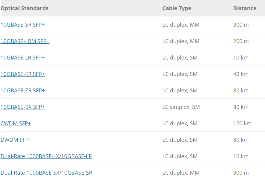
There are a variety of 10GBASE SFP+ transceivers according to the IEEE standard. For short transmission distances, you can choose 10GBASE-SR SFP+ transceiver or 10GBASE-LRM SFP+ transceiver, which can support transmission distance up to 300 meters and 220 meters over multimode fiber cables separately. 10GBASE-SR SFP+ transceiver module, working in wavelength of 850nm, is the most commonly used transceiver type for short distance transmission. For long distance transmission, there are also multiple choices of 10G SFP+ transceiver modules for you, such as 10GBASE-LR SFP+ transceiver, 10GBASE-ER SFP+ transceiver, 10GBASE-ZR SFP+ transceiver, CWDM SFP+ transceiver, DWDM SFP+ transceiver, BiDi SFP+ transceiver, etc. These transceiver modules can support transmission distances ranging from 10 km to 120 km over single-mode fiber cables.
And there is a special type of 10G SFP+ transceiver known as dual-rate SFP+ transceiver. A dual-rate SFP+ transceiver is a kind of optical transceiver which can support two different data rates. For example, Intel E10GSFPSR compatible dual-rate 1000BASE-SX and 10GBASE-SR SFP+ transceiver can be adjusted to support both 1G and 10G data rate up to 300m over OM3 multi-mode fiber. 1G/10G dual-rate SFP+ transceiver is common dual-rate optical transceiver in today's 10G SFP+ transceiver market. With dual-rate optical transceivers, users can achieve the full forward and backward compatibility of their systems at a low cost.
During the selection of fiber optic patch cables for 10G SFP+ transceivers, the transmission distance is the first element to consider. Single-mode fiber optic patch cables are used for long distance transmission and multi-mode fiber optic patch cables are designed for short distance transmission. Then you need to take the transmitting and receiving ports on the SFP+ transceivers into consideration. Most 10G SFP+ transceivers use duplex LC port, and BiDi SFP+ transceivers use simplex port. Thus, based on the port type on the SFP+ transceiver, simplex LC fiber patch cords or duplex LC fiber patch cords are chosen accordingly . The following chart introduces detailed cabling information for 10G SFP+ transceivers.
Though the era of 40/100 GbE is approaching, 10GbE still accounts for a large proportion of the market. SFP+ transceiver modules provide an efficient way for connecting your 10G networks. This post shares some basic information of 10G SFP+ optics and cabling information. For more specific information, please visit FS.COM, where you can find a variety of 10G SFP+ optics.
Posted by: jowang at
03:35 AM
| No Comments
| Add Comment
Post contains 690 words, total size 6 kb.
May 18, 2016
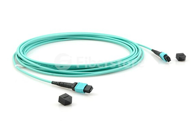
MPO cable, one commonly used type of fiber optic jumper cables, has now become a preferable cabling solution for the ever-increasing data center bandwidth requirements. MPO cable links feature parallel transmission and they are able to handle bandwidth all the way up to 100 Gbps. MPO cables are compact, pre-terminated, and plug-and-play by design. Though MPO cables have all these advantages, the testing abd certification of them could be very challenging. This article will focus on the MPO cable testing in the data center.
To get a better understanding of challenges of MPO cable validation, it is essential to know MPO cables and how they are tested. An MPO connection is about the size of a fingernail and contains 12 optical fibers, each has a smaller diameter than a human hair, and each needs to be tested separately. The actual fiber test is quick enough, typically under 10 seconds per fiber once you're in process.
One challenge is that pre-terminated fiber can be guaranteed functional as it is in the manufacturer's factory, but then it must be transported, stored, and later bent and pulled during installation in data centers. All kinds of performance uncertainties are introduced before fiber cables are deployed. Proper testing of pre-terminated cables after installation is the only way to guarantee their performance in a live application. Testing and determining fiber polarity is another challenge. The simple purpose of any polarity scheme is to provide a continuous connection from the link's transmitter to the link's receiver. For array connectors, TIA-568-C.0 defines three methods to accomplish this: Methods A, B and C. Deployment mistakes are common because these methods require a combination of patch cords with different polarity types.
Over the past years, more and more data centers have chosen MPO cables for trunking 10G connections. That trunking requires use of a cassette at the end of the MPO cable designed to accommodate legacy equipment connections. Now 40G and 100G connections are coming on the market. A migration path has emerged: removing the 10G cassette from the MPO cable and replacing it with a bulkhead to accommodate a 40G connection, then it might be possible to remove that bulkhead and do a direct MPO connection for 100G. The problem is that this migration strategy may be an efficient way to leverage the existing cabling, but in comparison to 10G connection, 40G and 100G standards call for different optical technology (parallel optics) and tighter loss parameters. In a word, you need to verify the links to ensure the required performance when you have a migration for your network.
The standard testing process of MPO cables can be time-consuming and error-prone. Once you throw polarity of all 12 fiber connections into the mix, it is almost a hit-and-miss manual affair. Upgrading from 10 Gbps to 40/100 Gbps, you need to test and validate performance all over again. What is the proper process of an MPO cable test? The answer is simple. Test all the 12 fibers—the whole cable—simultaneously and comprehensively (including loss, polarity). That sort of test capability changes the fiber landscape, and enables installers and technicians to efficiently validate and troubleshoot fiber—flying through the process by tackling an entire 12-fiber cable trunk with the push of a button. Tools to perform the test are emerging on the market, promising to reduce time and labor costs up to 95% over individual fiber tests. Several characteristics to consider when selecting a test tool:
- A single "Scan All" test function that delivers visual verification via an intuitive interface for all 12 MPO fibers in a connector.
- An onboard MPO connector to eliminate the complexity and manual calculations associated with a fan-out cord.
- Built-in polarity verification for end-to-end connectivity of MPO trunk cables.
- "Select Individual Fiber" function that enables the user to troubleshoot a single fiber with more precision.
Fast and reliable delivery of critical applications has been driving data center technology to evolve at an ever-increasing pace. The insatiable need for bandwidth ensures that the integrity of the data center has become inextricably linked to the strength of the fiber cabling infrastructure. The growing use of MPO trunk cables means that it's time to stop the cumbersome verification of individual fibers. After all, it's a single MPO connection. You should be able to test the MPO connection as a whole.
Posted by: jowang at
04:19 AM
| No Comments
| Add Comment
Post contains 741 words, total size 6 kb.
May 16, 2016
As bandwidth demands continue to grow, network service providers are looking at even higher networks of 100 Gigabit Ethernet (100GbE) to accommodate the constant traffic surge. 100 GbE is a group of computer networking technologies for transmitting Ethernet frames at rates of 100 gigabits per second (100Gbit/s). With the growing technology, the business case for 100 Gigabit Ethernet is becoming inescapably compelling. The 100G market has risen. QSFP28, as a new form factor, becomes more and more popular in the 100G transceiver market. What is QSFP28 transceiver? Why QSFP28 transceivers are popular in 100GbE networks? This post will give a brief introduction to QSFP28 transceiver in 100GbE networks.
QSFP28 transceiver is designed for 100G speeds and using the 4×25 wiring specification. The QSFP28 is the exact same footprint as the 40G QSFP+. The "Q" is for "Quad"; just as the 40G QSFP+ is implemented using four 10-Gbps lanes, the 100G QSFP28 is implemented with four 25-Gbps lanes. In all QSFP versions, both the electrical lanes and the optical lanes operate at the same speed, eliminating the costly gearbox found in CFP, CFP2, and the CPAK. The QSFP28 module has an upgraded electrical interface to support signaling up to 28 Gbps signals, yet keeps all of the physical dimensions of its predecessor.
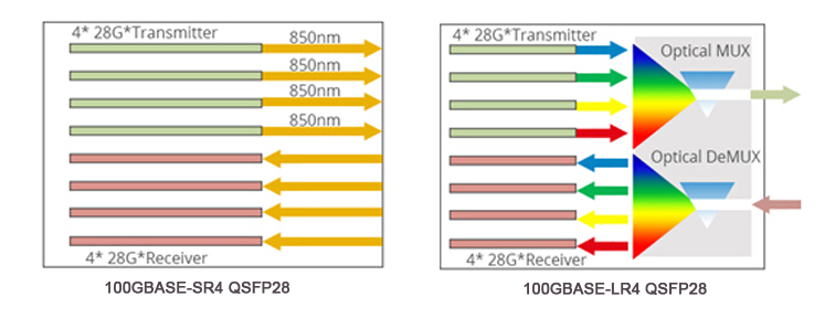
Two basic versions of QSFP28 transceivers are 100GBASE-SR4 QSFP28 transceiver and 100GBASE-LR4 QSFP28 transceiver, which are respectively used for multimode fiber (MMF) and single-mode fiber (SMF) 100G applications. The following pictire shows working principles of these two type of QSFP28 transceivers.
QSFP28 transceiver makes deploying 100GbE networks easy as 10GbE networks, having a strong ability to increase density, decrease power consumption, and decrease price per bit. It becomes a universal preferred data center form factor for several reasons.
1. QSFP28 transceiver increases front-panel density over QSFP+ transceiver. It has the same form factor and the maximum number of ports with QSFP+ transceiver, but the lane speeds are increased from 10 Gbps to 25 Gbps. Thus, QSFP28 transceiver increases front-panel density over QSFP+ transceiver. And the increase in panel density is even more dramatic when compared to some of the other 100 Gbps form factors, 450% versus the CFP2 and 360% versus the CPAK.
2. There are limitations of other versions of 100G transceivers. For example, in the first generation of 100GbE switches and routers, the smaller CXP form factor was used for cabling and the CFP or CFP2 was used for transceivers. This forced huge equipment design sacrifices. A switch with CXP ports couldn't be used in a data center with single-mode fiber (SMF). A router using CFP2 or CPAK ports had bandwidth limited by the 8-10 ports that could fit on the front panel.
3. With QSFP28 transceivers, a one rack-unit switch can accommodate up to 36 QSFP ports. Many more varieties of transceivers and cables can plug into these ports. The cables can be either copper direct attach cables (DACs) or active optical cables (AOCs).
4. QSFP28 transceivers can use either VCSELs (useful for shorter distances on MMF) or silicon photonics (for longer distances on SMF). Silicon photonics enables QSFP28 transceivers to support any data center up to 10 kilometers, and provide a high degree of integration. Silicon photonics is low power; even WDM (wavelength division multiplexing) designs can fit within the 3.5W maximum of QSFP.
At present market, the form factors of 100G transceiver module include CXP, CFP, CFP2, CPAK, CFP4 and QSFP28. Among them, QSFP28 demonstrates its great superiority. It increases density and decreases power and price per bit. QSFP28 transceiver has a great market prospect. And the coming generations of high-bandwidth switches, routers, and adapters will all feature QSFP28 ports to better adapt the 100G (or beyond) network demands. Fiberstore provides you with all kinds of QSFP28 optics with high quality. You can buy from us with confidence.
Posted by: jowang at
03:56 AM
| No Comments
| Add Comment
Post contains 648 words, total size 5 kb.
May 11, 2016
40GbE (Gigabit Ethernet) is an Ethernet standard developed by the IEEE 802.3ba task force. It enables the transfer of Ethernet frames at speeds of up to 40 gigabits per second (Gbps) and addresses physical layer specifications for communication across backplanes, copper cabling, multimode fiber and single-mode fiber. 40GbE standard has now been a new generation of high-speed and high-demand computing applications. Like 1GbE and 10GbE networks, the heart of the 40GbE network layer is a pair of transceiver modules which are connected by a patch cable. Transceiver modules and patch cables seem to be two basic components for 40GbE transmission. In this post, those two kinds of components for 40GbE transmission will be introduced.
40GbE transceivers are being developed along several standard form factors.
CXP TransceiverThe CXP form factor transceiver provides twelve lanes in each direction. It has a smaller size than the CFP transceiver. CXP transceiver serves the needs of multimode optics and copper. The Roman number "X" means that each channel has a transmission rate of 10 Gbps. CXP is a kind of hot-pluggable transceiver with data rate up to 12×10 Gbps.
CFP TransceiverThe CFP (C form-factor pluggable) transceiver also features twelve transmit and twelve receive 10Gbps lanes to support one 100GbE port, or up to three 40GbE ports. It is suitable for the needs of single-mode optics and can easily serve multimode optics or copper as well.
QSFP/QSFP+ TransceiverThe QSFP/QSFP+ (quad small-form-factor pluggable) transceiver has similar size with the CXP transceiver. It provides four transmit and four receive lanes to support 40GbE applications for multi-mode and single-mode fiber and copper today. QSFP+ transceiver is the most popular interface of 40G transceivers now. Two main types of QSFP+ transceivers are commonly used in the data center: short reach (QSFP-40G-SR4) for ~100 meters transmission on multimode fiber and long reach (QSFP-40G-LR4) for 100 meters to 10km using single-mode fiber. And there are other types of QSFP+ modules according to different objectives, such as 40GBASE-ER4, 40GBASE-LX4 (like JNP-QSFP-40G-LX4), 40GBASE-PLRL4 QSFP+, etc.
Fiber optic cable and copper cable are two mainly cabling choices for 40 GbE. OM3 and OM4 multi-mode fiber optic cables are generally recommended for 40GbE data center applications. They support a wider range of deployment configurations compared to copper cabling. The cost of using OM3 and OM4 multimode cabling solution is lower than the single-mode cabling solution. The supportable channel length depends on the cable and the transceiver type. With regard to connectors, MPO/MTP connectors for multimode transceivers can support multifiber parallel optics channels.
DAC and AOCDirect attach copper cable (DAC) and active optical cable (AOC) are ideal solutions for short-distance interconnection. They are widely used in data centers. Especially 40G QSFP+ breakout cables, with various of advantages compared with copper solutions and transceiver modules, are cost-effective solutions for 40GbE.
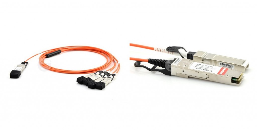
40G DAC includes active DACs and passive DACs. 40GbE passive copper cables provide robust connections for 40G systems and have low power consumption which improves data center power consumption and thermal efficiency, which makes them ideal for 40G LAN, HPC and SAN applications. QSFP+ to QSFP+ passive copper cable and QSFP+ to 4SFP+ passive breakout copper cable (such as QSFP-4SFP10G-CU3M) are two common types of QSFP+ passive DAC cables. 40G AOC is a type of active optical cable for 40GbE applications that is terminated with 40GBASE QSFP+ transceiver on one end while on the other end, it can be terminated with QSFP+ connector, SFP+ connector, or LC/SC/FC/ST connector. QSFP+ AOC integrates four data lanes in each direction with 40Gbps aggregate bandwidth. Each lane can operate at 10Gbps with lengths ranging from one to 100m. It is compliant with the QSFP MSA and IEEE P802.3ba. The following picture shows a Cisco QSFP-4X10G-AOC5M compatible 40G QSFP+ to 4x10G SFP+ active optical cable.
Unlike traditional Ethernet standard which has relied upon duplex fiber cabling with each channel using one fiber to transmit and the other to receive, 40GbE standard uses parallel optics for transmission. A 12-fiber cabling solution with each channel featuring four dedicated transmit fibers and four dedicated receiver fibers is used for 40GbE. The middle four fiber generally remain unused.
40GbE optics now are popular in data center and the market of 100GbE is accelerating. As products become less expensive and more available over time, 40 GbE and 100 GbE will evolve and become more popular in the next three to seven years. This post provides a quick and simple overview of 40GbE fiber optic components of the interconnected foundation. Hopes it can help you have a general idea of 40GbE.
Posted by: jowang at
06:03 AM
| No Comments
| Add Comment
Post contains 773 words, total size 6 kb.
May 09, 2016
When reading specifications of an SFP transceiver, such as Allied Telesis AT-SPSX compatible 1000BASE-SX SFP transceiver, you will come across words like "hot-swappable" or "hot-pluggable". What does "hot-swappable" mean? And how does it work? Many optical transceivers now in the optics market are with "hot-swappable" function, which can also be called as "hot-pluggable" function. People may generally consider it just a function that will help them save money or make their work more convenient. In fact, there are several things you need to learn about hot-swappable function of optical transceiver modules.
Hot-swappable optical transceiver module, is an optica component with a function that can support inserting or pulling out the module without shutting down the system or without significant interruption to the system or significant interruption to the operation of the system. "Hot-swappable" function can help us to avoid complete redesigns and cutdown the exorbitant costs associated with the practice, e.g. system updating. Now, optical transceiver modules, such as SFP (small form-factor pluggable), SFP+ (small form-factor pluggable plus), and 40G QSFP (quad small form-factor pluggable) are all hot-swappable transceivers. The following picture shows an HP J4859C compatible 1000BASE-LX hot-swappable SFP transceiver.
Optical transceiver module is an important and indispensable component in an optical transmission system. If we used a "non-hot-swappable" optical transceiver for management or upgrading of a network, we should power down or shut down the system until we finish the pluggable process. However, if cutting power of telecommunication and data transmission systems for a long time, there will be a great loss. In addition, the restart time of some operation systems is long, which will also lead to a big loss. This is why it is so important to find devices that are hot-swappable. Nowadays, hot-swappable technologies have been widely used in data communication and transmission industries and become more and more important.
Before adding the "hot-swappable" function to optical transceiver modules, several problems must be solved to ensure that those optical transceivers can function well. First, safety of the laser should be guaranteed. Laser is the most important and expensive part of an optical transceiver module. It is easy to be damaged and vulnerable to static electricity damage as it is a static sensitive component. Besides, surge current and system bus should be taken into consideration to avoid damage to components of optical transceivers and interference to data transmission.
To solve those problems, a few technologies are used to ensure safety and feasibility of hot-swappable optical transceiver modules. MSA (Multi-source Agreement) defines the use of TX fault (transmitter fault) to indicate whether an optical transceiver module can work in good condition or not. When inserting an optical transceiver, there is an initializing program. The optical transceiver will begin to test by itself after the power is on. If the self test is approved, it will dirve the IC (integrated circuit) to offer current to the laser, and then the laser works. Otherwise, it will not offer current to the laser. In addition, adding a shutdown pin to the circuit which can close the LD (laser diode) when failure occurs is also a solution to ensure the saftey of the laser. Meanwhile, to reduce the surge current, you can use a specific sequence of power. Moreover, you can also add a filter circuit as well as current limit switch to further reduce the surge current. Lastly, pull-up resistors and and precharge technologies are usually employed to reduce the interference of hot-swappable module on the system bus. These are also defined by the MSA.
The content above explains why "hot-swappable" optical transceiver modules are popular with users. Hope it will help you understand more about the "hot-swappable" function of optical transceivers. "Hot-swappable" function is of important value to an optical transceiver module now. Hot-swappable optical transceiver modules can reduce expenditures for companies, especially when devices fail prematurely because they have to shut down the system completely to replace the device. They have more flexibility and functionality, which can help companies to save both money and time. In a word, hot-swappable optical transceiver module is a great choice.
Posted by: jowang at
04:32 AM
| No Comments
| Add Comment
Post contains 699 words, total size 5 kb.
May 05, 2016
Gradually, 1G and 10G data rates are becoming not adequate enough to meet the high-bandwidth application needs. 40G Ethernet provides a good solution and plays an important role for the transition from 10G Ethernet to 100G Ethernet. It has been a very preferable option now. Products for 40G Ethernet such as 40G QSFP+ transceivers, 40G QSFP+ direct attach copper (DAC) cables and active optical cables (AOCs) are very popular in the market. 40G QSFP+ DACs and QSFP+ AOCs are cost-effective alternative solutions in short reach interconnections. In this post, a detailed introduction to 40G QSFP+ DACs and QSFP+ AOCs will be given.
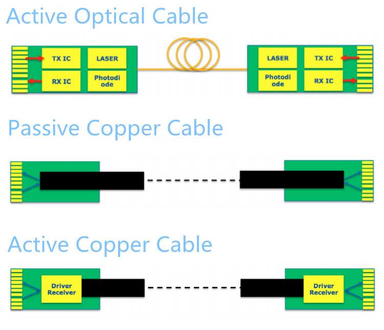
40G QSFP+ DACs and QSFP+ AOCs are two kinds of optical transceiver assemblies, which are terminated with transceiver-style plugs to be used in the same ports where optical transceivers are used. QSFP+ AOCs, such as Cisco QSFP-H40G-AOC1M compatible 40G QSFP+ AOC, are active devices, which incorporate active electrical and optical components to boost/receive signal via optical fiber. QSFP+ DACs can be both passive and active. Passive DACs (often called PCCs), such as Cisco QSFP-4SFP10G-CU3M compatible 40G QSFP+ to 4x10G SFP+ passive DAC, have no active circuitry, which means there is a direct connection between copper cable and QSFP+ transceiver's printed circuit board (PCB) electrical contacts. Active DACs (often called ACCs) incorporate active component to boost/receive signal via copper cable. The following picture shows the general internal structure of AOCs and DACs.
QSFP+ DACs and QSFP+ AOCs are ideal solutions for short-distance interconnection, and they are widely used in data centers. This part will talk about advantages and disadvantages of QSFP+ DACs and QSFP+ AOCs respectively.
QSFP+ DACsNowadays people may think that copper technology is out of fashion compared to fiber technology. It is not true for QSFP+ DAC cables. QSFP+ DACs still get their roles in the market for the following advantages.
- Interchangeability—QSFP+ DACs are interchangeable and hot swappable with fiber optic modules.
- Enough data rate for various applications—QSFP+ DAC cables can support higher data rates than traditional copper interfaces. QSFP+ DAC cables offer a cost-effective way to establish a 40G link between QSFP+ ports of QSFP+ switches within racks and across adjacent racks.
- Low cost—Copper cables are much cheaper than fiber cables, which makes QSFP+ DACs a cost-effective solution for short reach applications.
The defect of QSFP+ DACs is that they are heavy and bulky, making them difficult to be managed. Furthermore, due to the nature of electrical signals, DAC cables are vulnerable to the effects of electromagnetic interference (EMI), such as undesirable responses, degradation, or complete system failure.
QSFP+ AOCsOffering reliable transport for aggregated data rates up to 40 Gbps, QSFP+ AOCs provide customers with flexibility of traditional optical modules by interfacing to systems via a standard QSFP MSA connector. QSFP+ AOCs are premium products, offering several benefits, as shown below.
- Great bandwidth—QSFP+ AOCs have a throughput of up to 40 Gbps with QSFP+ transceivers. They are ideal for the high density signal transmission in most data centers and high performance computing applications.
- EMI immunity—Optical fiber is a kind of dielectric (not able to conduct electric current), QSFP+ AOCs are immune to electromagnetic energy.
- Light weight—Fiber cables are lighter than copper cables. QSFP+ AOC weighs less than a comparable DAC cable.
Compared with QSFP+ DAC cables, the drawback of QSFP+ AOCs is that they may be a little more expensive for customers.
40G QSFP+ DACs and QSFP+ AOCs use the same port as an optical transceiver but provide you with significant cost and power savings in short reach applications. They can fill the need for short, cost-effective connectivity and provide a power-efficient and cost-effective replacement to 40G optical transceivers. Fiberstore offers you a large range of QSFP+ DACs and QSFP+ AOCs with high quality for your 40G applications.
Posted by: jowang at
06:47 AM
| No Comments
| Add Comment
Post contains 646 words, total size 5 kb.
May 03, 2016
Sometimes, we may see this kind of description: This Allied Telesis AT-SPSX compatible SFP transceiver is a 1000BASE-SX SFP 850nm 550m transceiver module, and it is fully compatible with MSA SFP specification. What does MSA mean? It seems like a standard to define optical transceivers. Actually, MSA is an agreement which equipment vendors assume when developing form factors, usually called transceiver modules, for communication interfaces. In this post, some basic knowledge of the MSA will be provided.
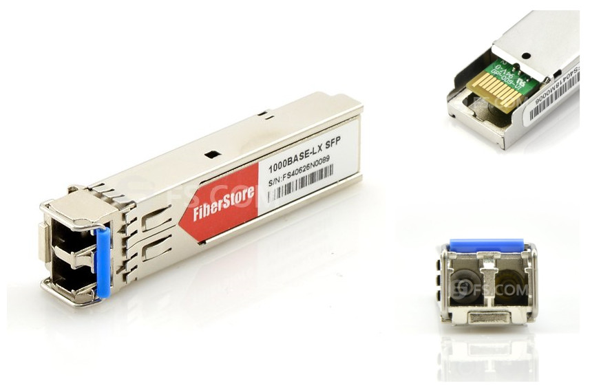
MSA stands for multi-source agreement. It is an agreement among multiple manufacturers to make products compatible across vendors, acting as de facto standards and establishing a competitive market for interoperable products. Products that adhere to MSAs include various fiber optic transceivers (such as SFP, SFP+, XENPAK, QSFP, XFP, etc), fiber optic cables, and other networking devices. For example, HP J4859C compatible SFP transceiver, as shown below, is a 1000BASE-LX SFP 1310nm 10km DOM transceiver module, which is fully compatible with MSA SFP specification. MSA strictly defines the operating characteristics of those optical transceivers so that system vendors can implement ports in their devices which allow MSA compliant optical transceivers produced by the name brand, as well as third party vendors, to function properly. That is to say, optical transceivers can be purchased from multiple sources in the open market. MSA is also very important in the cabling industry as the density, line speed, power consumption and typical cost of a cabling can strongly impact its success in the marketplace, which in turn, can drive the choice for both connector and media type.

When designing their communication systems, equipment vendors all rely on MSAs to ensure interoperability and interchangeability between interface modules. With MSAs, suppliers can produce optical transceiver modules with the same functions. For this reason, there are many module suppliers for customers to choose. Freedom of choice lays the foundation of the efficient operation of markets. To gain a larger share of the market, suppliers may act as efficiently as possible, which will drive down costs and offer wide options to customers. Besides, with so many excellent 3rd party optical transceiver module suppliers in the market, network operators don't need to purchase optical transceivers directly from system (original brand) vendors, which will also save huge costs. Finally, there is no doubt that all those factors will help support and encourage creation and adherence to standards at the same time. Over the past decade, the MSA process has helped accelerate the acceptance of modules such as SFP+ and CFP, allowing optical transceivers to support greater bandwidth such as 40G and 100G.
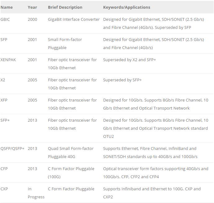
MSA is a popular industry format jointly developed and supported by many network component vendors. Many common optical transceivers are specified by it at present. MSAs usually specify parameters for optical transceivers and their guideline values, such as the electrical and optical interfaces (e.g. SX, LX, EX, ZX, etc), mechanical dimensions, electro-magnetic values and other data. This data is accessible by the host system over the I2C interface, as is the status of the optional DDM functions. Some approved fiber optic transceiver multi-source agreements are listed in the following table:
MSA is an agreement between multiple manufacturers to make products which are compatible across vendors. There are many kinds of products that adhere to MSAs, such as SFP and SFP+ optical transceiver devices are 'standardized' by multi-source agreements. MSAs provide you with a lot of options. Optical transceivers and fiber optic patch cords may be purchased from any of the multiple sources in the open market.
Posted by: jowang at
06:10 AM
| No Comments
| Add Comment
Post contains 600 words, total size 5 kb.
32 queries taking 0.1016 seconds, 86 records returned.
Powered by Minx 1.1.6c-pink.

