


November 29, 2016
In order to meet data center challenges, saving space ad increasing density becomes more critical than ever. High-density fiber patching solutions offer higher performance and reliability. Using a comprehensive solution of high-density fiber optic enclosures or patch panels with either adapter panels or pre-terminated cassettes provides a complete fiber cross-connect patching solution in dense networking areas.

The fiber patch panel, or fiber enclosure, is built and designed for efficient cable organization, management and protection within the racks. High-density fiber patch panel consists of a panel enclosure and modular HD cassettes, which can connect a 40G/100G fiber network feed (using MTP cable) and segment it into standard LC connections in order to interface with 10G devices. The cassettes are housed in a space-saving, rack-mountable, panel enclosure that can hold different amounts of cassettes, depending on the installation requirements.
The high-density patch panel can provide fast and easy deployment of high-density interconnects and cross-connect in data centers. The following are some advantages of using high-density fiber patch panels.
Simplify Cabling Deployment: With the fiber patch panel in place, there is no need to run long jumpers across the room, under the floor or in overhead conveyance. You only need to run a short fiber patch cable instead from your SAN or network switch up to the fiber patch panel/enclosure.
Space-saving: High-density fiber patch panel is one of the best space savers in the data center. It helps to increase port density by allowing you to fit more cables into a smaller space. Most importantly, it allows you to save space and stay organized.
Increase Port Density: Besides better space optimization, high-density patch panel can achieve double the port density in 1U of rack space. This allows for density increases and technology changes without a complete tear-out and replacement of existing infrastructure.
Ease of Installation: As described above, cassette is a part of the patch panel. When installing the cassette, no tools are required in the panel enclosure. And using push-pull tabs, connections can easily be locked or unlocked in the panel. Each cassette features factory terminated connectors that reduce the time and labor required of field connector terminations.
Flexibility and Adjustability: Fiber patch panels can connect different generations of equipment, such as 10G, 40G, 100G in a simple panel-cassette system. And network reconfigurations are highly adjustable due to the modular cassette system.
Cost-effective Solution for 40G/100G Network: Employing a high-density fiber patch panel is the most effective solution for overcoming cabling congestion associated with 40G/100G network connections as the modular plug-and-play cassettes can be changed when higher bandwidth becomes needed. It can manage, allocate and control the connections of network equipment of varying bandwidths. Cable management is simplified because the fiber patch panel can be changed or expanded by installing a new cassette instead of running new cables. By simply patching the 40G MTP cables at the back and the standard LC patch cable to devices in the front of the cassette, the IT staff don’t need to pull a new fan-out cable each time they need a new connection. Modular cassettes allow to expand whenever you need to accommodate the necessary bandwidth and connectors.
To meet the demands for high density in today’s market, FS.COM has developed comprehensive high density solutions of FHD Series Fiber Enclosures, Adapter Panels, Pre-terminated MTP Cassettes for 10G/40G/100G applications. And the newly introduced LC HD+ cable assemblies combine high density with manageability and ease of making moves, adds and changes, addressing the pressing need of data centers and communication rooms to save space and energy. For more details, kindly visit the page LC HD+ Cables.
Posted by: jowang at
08:13 AM
| No Comments
| Add Comment
Post contains 619 words, total size 5 kb.
November 24, 2016
Plesiochronous Digital Hierarchy (PDH) system was the earliest stand used to transport phone calls and data over the same fiber. With the increasing demand of phone calls and data traffic, SONET/SDH are then introduced to replace PDH system to transport the data without synchronization problems. As you can see, SONET/SDH SFP+ transceivers have been widely used in the market. This post will give a brief analysis on SONET/SDH SFP+ transceivers.
SONET (Synchronous Optical Networking) and SDH (Synchronous Digital Hierarchy) are multiplexing protocols that transfer multiple digital bit streams over optical fiber with lasers or light-emitting diodes (LEDs). SONET and SDH are widely used methods today for very high speed transmission of voice and data signals across the numerous world-wide fiber-optic networks. SONET is the standard used in the United States and Canada, and SDH in the rest of the world. The two are largely equivalent. Although the SONET standards were developed before SDH, it is considered a variation of SDH because of SDH’s greater worldwide market penetration.
We often find SONET/SDH SFP transceiver like Cisco OC-3/STM-1 LR-1 SFP 1310nm 40km IND DOM. What does OC-3/STM-1 mean? OC-3c (Synchronous Transport Signal 3, concatenated) is the basic unit of SONET. Depending on the system, OC-3 is also known as STS-3 (when the signal is carried electrically). STM-1 (Synchronous Transport Module, level 1) is the basic unit of framing in SDH, which operates 155.52 Mbit/s. OC-3c and STM-1 have the same high-level functionality, frame size, and bit-rate.
10 Gigabit Ethernet (10GbE) means the Ethernet network runs at 10 Gigabit per second. The 10 Gigabit Ethernet defines two PHY (Physical Layer) types: a local area variant (LAN PHY) with a line rate of 10.3125 Gbit/s, and a wide area variant (WAN PHY) with the same line rate as OC-192/STM-64 (9,953,280 Kbit/s).
10GbE provided the potential for an Ethernet solution aligned with the data rate of OC-192 backbone. It’s the first time in Ethernet history that no additional speed matching equipment would be required to link with the WAN. A seamless end-to-end Ethernet network can be built with less money. But the question is how to balance the compatibility with the installed base of OC-192 equipment while still meeting the economic feasibility criteria of the P802.3ae Task Force in defining the 10GE WAN PHY. To solve this problem, an OC-192 frame format is provided to support only the SONET overhead features required for fault isolation. This simplification avoids unnecessary functions and cost.
In order to make sure that WAN PHY optics would benefit from the high volumes and low cost of Ethernet, the serial 1310 nm and 1550 nm transceiver modules were kept the same as the LAN PHY. Since the 1310 nm and 1550 nm transceiver modules are designed for up to 10km and 40 km links respectively, they will inter-operate with OC-192 transceiver modules for 1310 nm and 1550 nm over intermediate reach, respectively.
FS.COM supplies OC-192/STM-64 SFP+ for short reach (SR-1, VSR) , intermediate reach (IR-2) and long reach (LR-2) applications. These SFP+ modules are compatible with the SONET/SDH and ATM standards. For more details, please visit the website at fs.com.
Posted by: jowang at
08:10 AM
| Comments (2)
| Add Comment
Post contains 536 words, total size 4 kb.
November 18, 2016
Although the widely acknowledged Ethernet speed upgrading path was 10G-40G-100G, web-scale data centers and cloud based services need servers with above 10GbE capability and cost sensitive for nearer-term deployment. It indicates that the latest path for server connection willbe 10G-25G-100G with potential for future upgrading to 400G. But why 25G is in demand? Because in the high-density data center, using multiple 10 GbE would require twice as many Ethernet switches with their associated space, power, and cooling costs. Deploying 25GbE networks enables organizations to significantly decrease capital and operating expenses by reducing the required number of switches and cables to solve these issues, compared to 10GbE and 40GbE (4×10 GbE) technology. It is just under this circumstance that QSFP28 and SFP28 for 25 Gigabit Ethernet are promoted.
25GbE (25 Gigabit Ethernet) is a proposed standard for Ethernet connectivity in a data center environment. An industry consortium (25G Ethernet Consortium) was formed in July 2014 to support the specification of single-lane 25Gb Ethernet technology, because the proposed 25 GbE standard will use the same physical silicon from a single 25 Gbit/s lane. This simplifies the process with just minor changes for forward error correction and lane alignment, and it reduces the cost when compared to 40 GbE.
25GbE leverages technology defined for 100 Gigabit Ethernet implemented as four 25-Gbit/s lanes (IEEE 802.3bj) running on four fibers or copper pairs. For instance, if we use the 10GbE—40GbE—100GbE path, we will have 10 GbE single, 40 GbE quads and 100 GbE ten lanes in production. But when we turn to 25 GbE, we just need 25 GbE single, 50 GbE dual and 100 GbE quads in production. Obviously, 25GbE enables us to have 2.5X the performance of 10Gb Ethernet, making it a cost-effective upgrade to the 10GbE infrastructure. While compared to 40GbE, which is actually four 10GbE lanes, 25GbE is delivered across a single lane which provides greater switch port density and network scalability. Moreover, it is easy to upgrade of 50GbE and 100GbE networks using multiple 25GbE lanes. It is a cost-effective solution for datacenter upgrade and cloud-scale network expansion. This is why 25 GbE is favoured and highly recommended by those famous consortium.

The SFP28 (25G Small Form-Factor Pluggable) and QSFP28 (25G Quad Small Form-Factor Pluggable) transceivers and interconnect cables are high-density, high-speed product solution designed for 25GbE and 100GbE applications in the telecommunications, data center and cloud-scale networks. The emergence of these two form-factors pluggable certainly reflect the trend in the industry to aggressively bring 100GE density up and costs down.
Based on the SFP+ MSA form-factor, SFP28 assembly solution enables a new generation of high-density 25G Ethernet switches and NIC cards, facilitating server connectivity in data centers, and a conventional and cost-effective upgrade path for enterprises deploying 10G Ethernet links today in the ubiquitous SFP+ form factor.
QSFP28 transceiver, as a new type of 100G transceivers, offers four channels of high-speed differential signals with data rates ranging from 25 Gbps up to potentially 40 Gbps, and will meet 100 Gbps Ethernet (4×25 Gbps) and 100 Gbps 4X InfiniBand Enhanced Data Rate (EDR) requirements. According to IEEE 802.3bm, the 100GBASE-SR4 QSFP28 is designed for multimode application and support maximum link length of 100 m over OM4 Fiber. The 100G QSFP28 LR4 module is designed for single-mode application which support maximum link length of 10 km over SMF. QSFP28 has the same footprint and faceplate density as QSFP+ and is just slightly smaller than CFP4. Theoretically, QSFP28 seems to have the density advantage over CFP4, but CFP4’s higher maximum power consumption gives it the advantage on longer reach optical distances. As the two main types of 100GbE transceivers, each of them has its own merits. Only time will tell how this all plays out.
Through the above analysis, we can see that, 25 GbE solution is more suitable for the high-density data center. But at present, for long distance transmission, the existing 40/100GbE solution—QSFP/QSFP+ and CFP family (CFP, CFP2, CFP4) seems to be better. FS.COM offers a comprehensive solution of fiber optic transceivers and cable assemblies. For data center, we offer a full product line of basic transceiver optics, such as 1000BASE-SX, 1000BASE-LX/LH SFPs, 10GBASE-LR SFP+ etc. We also offer high-density interconnection solution by launching whole series of 40GBASE QSFP+ optics and 100GBASE-LR4 CFP2 and CFP4 optics as well as the cable assemblies.
Posted by: jowang at
07:10 AM
| No Comments
| Add Comment
Post contains 743 words, total size 6 kb.
November 14, 2016
As the most popular WDM technology, DWDM (Dense wavelength-division multiplexing) revolutionized data transmission technology by increasing the capacity signal of embedded fiber. This increase means that the incoming optical signals are assigned to specific wavelengths within a designated frequency band, then multiplexed onto one fiber. By providing channel spacings of 50 GHz (0.4 nm), 100 GHz (0.8 nm) or 200 GHz (1.6 nm), several hundreds of wavelengths can be placed on a single fiber. DWDM takes advantage of the operating window of the Erbium Doped Fibre Amplifier (EDFA) to amplify the optical channels and extend the operating range of the system to over 1500 kilometers. The following picture shows the operation of a DWDM system.
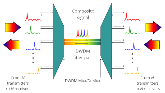
A typical DWDM system is composed of transmitter, receiver, optical amplifier, transponder, DWDM multiplexer and DWDM demultiplexer. They allow DWDM system to interface with other equipment and to implement optical solutions throughout the network, complying with the ITU channel standards.
- Optical transmitters/receiversTransmitters in DWDM systems provide the source signals which are then multiplexed. Multiple optical transmitters are used as the light sources in a DWDM system. We can also utilize a transceiver to replace transmitters and receivers to achieve the same purpose. Usually a DWDM transceiver applied in DWDM network can reach a transmission distance of up to 120km.
- Optical amplifiersOptical amplifiers (OAs) boost the amplitude or add gain to optical signals passing on a fiber by directly stimulating the photons of the signal with extra energy. They are "in-fiber†devices. OAs amplify optical signals across a broad range of wavelengths. This is very important for DWDM system application. Erbium-doped fiber amplifiers (EDFAs) are the most commonly used type of in-fiber optical fibre.
- TranspondersTransponders are designed to convert optical signals from one incoming wavelength to another outgoing wavelength suitable for DWDM applications. Transponders are optical-electricaloptical (O-E-O) wavelength converters. Within a DWDM system, a transponder converts the client optical signal back to an electrical signal (O-E) and then performs either 2R (reamplify, reshape) or 3R (reamplify, reshape, and retime) functions.A transponder is located between a client device and a DWDM system. From left to right, the transponder receives an optical bit stream operating at one particular wavelength (1310 nm). The transponder converts the operating wavelength of the incoming bitstream to an ITU-compliant wavelength. It transmits its output into a DWDM system. On the receive side (right to left), the process is reversed. The transponder receives an ITU-compliant bit stream and converts the signals back to the wavelength used by the client device.
- DWDM Multiplexers and DemultiplexersMultiple wavelengths (all within the 1550 nm band) created by multiple transmitters and operating on different fibers are combined onto one fiber by way of an optical multiplexer. The output signal of an optical multiplexer is referred to as a composite signal. At the receiving end, a demultiplexer separates all of the individual wavelengths of the composite signal out to individual fibers. The DWDM demultiplexers are capable of distinguishing each wavelength without crosstalk. The individual fibers pass the demultiplexed wavelengths to as many optical receivers. Typically, mux and demux (transmit and receive) components are contained in a single enclosure. Optical mux/demux devices can be passive. Component signals are multiplexed and demultiplexed optically, not electronically, therefore no external power source is required.

As occurs with many new technologies, the potential ways in which DWDM can be used are only beginning to be explored. Already, however, the technology has proven to be particularly well suited for several vital applications.
DWDM is ready made for long-distance telecommunications operators that use either point–to–point or ring topologies. The sudden availability of 16 new transmission channels where there used to be one dramatically improves an operator’s ability to expand capacity and simultaneously set aside backup bandwidth without installing new fiber.
This large amount of capacity is critical to the development of self-healing rings, which characterize today’s most sophisticated telecom networks. By deploying DWDM terminals, an operator can construct a 100% protected, 40 Gb/s ring, with 16 separate communication signals using only two fibers.
DWDM is the clear winner in the backbone. It was first deployed on long-haul routes in a time of fiber scarcity. Then the equipment savings made it the solution of choice for new long-haul routes, even when ample fiber was available. While DWDM can relieve fiber exhaust in the metropolitan area, its value in this market extends beyond this single advantage. Alternatives for capacity enhancement exist, such as pulling new cable and SONET overlays, but DWDM can do more. What delivers additional value is DWDM’s fast and flexible provisioning of protocol- and bit rate-transparent, data-centric, protected services, along with the ability to offer new and higher-speed services at less cost.
Posted by: jowang at
04:28 AM
| No Comments
| Add Comment
Post contains 788 words, total size 7 kb.
November 09, 2016
As new network architectures continue to demand ever higher speed, 40Gbps and 100Gbps Ethernet links are rapidly coming on line. In fact, volume is starting to build and switch port as well as transceiver prices are dropping rapidly. There are many new form factors for optical transceivers supporting a variety of transmission distances and fiber types. But they are not the prior focus of this post. Today, we’ll mainly bring two major trends to you. One major trend is the use of multiple parallel optical paths to achieve the total 40Gbps or 100Gbps interface transfer rate. The other is using multiple wavelengths and integrated wavelength division multiplexing to achieve multiple paths on single fibers.
Concerning modal dispersion when the speed is at or above 25Gbps, it is very challenging to achieve distance of more than 5 or 10 meters on multimode fibers. Therefore, most multimode transceiver implementations at 40G/100G use multiple parallel links each running at rates of 10Gbps or 25Gbps. While some may be familiar with the use of multi-fiber ribbon cables terminated with MPO connectors for interconnection between with fiber patch panels, these cables are now being used directly on 40G and 100G transceivers. Another result of moving more to parallel paths is expanded use of Direct Attached Cables (DACs, both fiber and copper). While DACs were somewhat popular as a low-cost alternative to fiber transceivers at 10Gbps, there increased bulk was a significant concern in some applications, like high density data centers. With the advent of ribbon fiber with MPO connectors on 40G/100G optical transceivers, the ‘bulk’ difference between copper and fiber connections is substantially lessened.
Since 40/100G Ethernet multimode QSFP modules use parallel optics technology which requires data transmission across multiple fibers simultaneously, multi-fiber connectors are needed. MPO (often referred to as MTP which is actually a brand name from US Conec) is the specified connector type for multi-mode 40/100G Ethernet. The fiber cable used with these connectors is typically OM3 although singlemode (OS1) is also in what are referred to as PSM (Parallel Single Mode) interfaces. Of course these connectors and cables are backward is compatible with legacy 1Gbps and 10Gbps interfaces.
The MPO connector is quite robust and features a keying mechanism so the connector only mates in on position. A common problem with previous duplex connectors (like dual-LC or dual-SC) is reversing of transmit and receive. Since the MPO connector contains both transmit and receive fibers and can only be assembled in a single orientation, this problem should be eliminated. A nice feature of the MPO connector is the audible locking "click†which occurs when the connector is seated. Also, the connector retention mechanism is very reliable. Once seated the connector cannot be separated without firmly grasping and pulling back on the plastic sleeve.
QSFP-40G-SR4 Ethernet uses a 12 position MTP/MPO connector interface. In the 12-fiber MTP/MPO connector, all these fibers are in a single row. The four leftmost fibers are used for transmit data, the middle four fibers are left unused, and the four rightmost fibers are used for receive data.
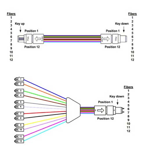
Three options are defined for the 100GBASE-SR10 Ethernet interface. This first two, shown below, use two separate 12 position MTP/MPO connectors, one for all of the Tx fibers and the other for the Rx fibers. Neither of these options appear to be actually used in commercial implementations. The 3rd option utilizing a 24 position MPO has become the de facto standard in the marketplace. The MPO is arranged in two rows of 12. The middle 10 fibers of each row are used while the outermost fibers at each end of the rows are vacant. 10 fibers in the upper row for transmitting data and the remaining 10 fibers in the lower row for receiving data.
Direct Attached Cables (DACs) are assemblies composed of a fixed length of copper or fiber cable with standard pluggable transceiver modules permanently fixed to each of its ends. There are many variations of DACs for a variety of 40G and 100G applications, among which 100G QSFP28 to 10X 10G SFP+ breakout cables and a 100G QSFP28 to 4X 25G QSFP are the most common variations.
The primary advantage of using DACs versus paired transceivers with a length of cable is cost savings. The biggest disadvantage is the fixed length of the assemblies. In applications where location of equipment is carefully planned in advance and link lengths are known quite accurately and will remain fixed over the life of the installation where DACs can be a very economical alternative.
As IT infrastructures migrate to 40G and 100G speeds, network designers must carefully weigh alternative implementations of such links. DACs are a low cost alternative to more flexible pluggable transceivers interconnected by fiber. New MPO connectors with their multi-fiber ribbon cables may be new an unfamiliar versus the ubiquitous SC and LC fiber connectors of the past. However, by understanding the keying and pinout arrangements of MPO connections, reasonable multimode and low cost singlemode connections are possible even at 40G and 100G speeds.
Posted by: jowang at
02:20 AM
| Comments (3)
| Add Comment
Post contains 849 words, total size 6 kb.
As new network architectures continue to demand ever higher speed, 40Gbps and 100Gbps Ethernet links are rapidly coming on line. In fact, volume is starting to build and switch port as well as transceiver prices are dropping rapidly. There are many new form factors for optical transceivers supporting a variety of transmission distances and fiber types. But they are not the prior focus of this post. Today, we’ll mainly bring two major trends to you. One major trend is the use of multiple parallel optical paths to achieve the total 40Gbps or 100Gbps interface transfer rate. The other is using multiple wavelengths and integrated wavelength division multiplexing to achieve multiple paths on single fibers.
Concerning modal dispersion when the speed is at or above 25Gbps, it is very challenging to achieve distance of more than 5 or 10 meters on multimode fibers. Therefore, most multimode transceiver implementations at 40G/100G use multiple parallel links each running at rates of 10Gbps or 25Gbps. While some may be familiar with the use of multi-fiber ribbon cables terminated with MPO connectors for interconnection between with fiber patch panels, these cables are now being used directly on 40G and 100G transceivers. Another result of moving more to parallel paths is expanded use of Direct Attached Cables (DACs, both fiber and copper). While DACs were somewhat popular as a low-cost alternative to fiber transceivers at 10Gbps, there increased bulk was a significant concern in some applications, like high density data centers. With the advent of ribbon fiber with MPO connectors on 40G/100G optical transceivers, the ‘bulk’ difference between copper and fiber connections is substantially lessened.
Since 40/100G Ethernet multimode QSFP modules use parallel optics technology which requires data transmission across multiple fibers simultaneously, multi-fiber connectors are needed. MPO (often referred to as MTP which is actually a brand name from US Conec) is the specified connector type for multi-mode 40/100G Ethernet. The fiber cable used with these connectors is typically OM3 although singlemode (OS1) is also in what are referred to as PSM (Parallel Single Mode) interfaces. Of course these connectors and cables are backward is compatible with legacy 1Gbps and 10Gbps interfaces.
The MPO connector is quite robust and features a keying mechanism so the connector only mates in on position. A common problem with previous duplex connectors (like dual-LC or dual-SC) is reversing of transmit and receive. Since the MPO connector contains both transmit and receive fibers and can only be assembled in a single orientation, this problem should be eliminated. A nice feature of the MPO connector is the audible locking "click†which occurs when the connector is seated. Also, the connector retention mechanism is very reliable. Once seated the connector cannot be separated without firmly grasping and pulling back on the plastic sleeve.
QSFP-40G-SR4 Ethernet uses a 12 position MTP/MPO connector interface. In the 12-fiber MTP/MPO connector, all these fibers are in a single row. The four leftmost fibers are used for transmit data, the middle four fibers are left unused, and the four rightmost fibers are used for receive data.
Three options are defined for the 100GBASE-SR10 Ethernet interface. This first two, shown below, use two separate 12 position MTP/MPO connectors, one for all of the Tx fibers and the other for the Rx fibers. Neither of these options appear to be actually used in commercial implementations. The 3rd option utilizing a 24 position MPO has become the de facto standard in the marketplace. The MPO is arranged in two rows of 12. The middle 10 fibers of each row are used while the outermost fibers at each end of the rows are vacant. 10 fibers in the upper row for transmitting data and the remaining 10 fibers in the lower row for receiving data.
Direct Attached Cables (DACs) are assemblies composed of a fixed length of copper or fiber cable with standard pluggable transceiver modules permanently fixed to each of its ends. There are many variations of DACs for a variety of 40G and 100G applications, among which 100G QSFP28 to 10X 10G SFP+ breakout cables and a 100G QSFP28 to 4X 25G QSFP are the most common variations.
The primary advantage of using DACs versus paired transceivers with a length of cable is cost savings. The biggest disadvantage is the fixed length of the assemblies. In applications where location of equipment is carefully planned in advance and link lengths are known quite accurately and will remain fixed over the life of the installation where DACs can be a very economical alternative.
As IT infrastructures migrate to 40G and 100G speeds, network designers must carefully weigh alternative implementations of such links. DACs are a low cost alternative to more flexible pluggable transceivers interconnected by fiber. New MPO connectors with their multi-fiber ribbon cables may be new an unfamiliar versus the ubiquitous SC and LC fiber connectors of the past. However, by understanding the keying and pinout arrangements of MPO connections, reasonable multimode and low cost singlemode connections are possible even at 40G and 100G speeds.
Posted by: jowang at
02:20 AM
| No Comments
| Add Comment
Post contains 849 words, total size 6 kb.
35 queries taking 0.0509 seconds, 82 records returned.
Powered by Minx 1.1.6c-pink.

