


February 17, 2017
Not all Ethernet cables are created equally. They are grouped into sequentially numbered categories ("catâ€) based on different specifications. Cat 5e, Cat 6, Cat 6a, Cat 7 cable are the most common kinds of Ethernet cables. How to tell the difference between them and choose the suitable one for your network?
First and foremost, let’s have a rough sketch of their characteristics. All network cabling consists of 8 wires; twisted, and made into 4 pairs, each color coded by a solid color with their respective dashed/striped white cables. Cat 5 cables are designed to support theoretical speed of between 10 Mbps and 100 Mbps. The Cat5e cable has lower crosstalk and provide a faster, reliable and steady speed than Cat 5 cable. Cat6 cables have more stringent specifications than Cat 5e cables and are capable of supporting 10 Gbps. They have slighter thicker wires, and the cores are more tightly twisted together. Cat 7 cables feature even more strict specifications for crosstalk and system noise than Cat 6. And shielding have been added for individual wire pairs on the Cat 7 cables. Here are some factors to consider when choosing these kinds of Ethernet cables.
STP (shielded twisted pair) cables simply have additional shielding material that is used to cancel any external interference that may be introduced at any point in the path of the cable. UTP (unshielded twisted pair) cables have no protection against such interference and its performance is often degraded in its presence. But both of them have interference canceling capacities.
Typically, using STP cables ensures that you can get the maximum bandwidth from your cabling even if the external condition is less than ideal. STP cables work by attracting interference to the shield, then running it off into a grounded cable. If the cable is improperly grounded, then its noise-canceling capabilities are severely compromised. Additionally, STP cables have bigger diameter than UTP cables, and they are more expensive. Besides, they are more fragile as the shield must be kept intact to ensure them work properly. STP cables are commonly used in industrial settings with high amounts of electromagnetic interference, such as a factory with large electronic equipment, where they can be properly installed and maintained. They can also be used in outdoor environments where the cables are exposed to the elements and man-made structures and equipment that may introduce additional interference.
UTP cables are smaller than STP cables, which makes them easier to install, particularly in bulk or in narrow spaces. They do not require the presence of a grounding cable and do not require much maintenance, but transmit data as fast as STP cables. Generally, UTP cables are more prone to noise than properly installed and maintained STP cables. They are more prevalent and popular used in domestic and office Ethernet connections, and in any area where there is not a high degree of electromagnetic interference.
Both solid and stranded Ethernet cables refer to the actual copper conductor in the pairs. The solid cable uses one solid wire per conductor, so in a standard Cat 5e or Cat 6 four pair (8 conductor) roll, there would be a total of 8 solid wires. Stranded cable uses multiple wires wrapped around each other in each conductor, so in a 4 pair (8 conductor) 7 strand roll (typical configuration), there would be a total of 56 wires.
Solid cables are most useful for structured wiring within a building. They can be easily punched down onto wall jacks and patch panels as they have only one conductor. The wire seats properly into insulation displacement connector. Solid cables are less useful when you are terminating with standard RJ45 connectors, as used when making patch cables. Most RJ45 connectors use 2 prongs which penetrate the conductor itself. This is not desirable, since solid cable has the tendency to break when penetrated by the prong. Using a 3 prong style RJ45 connectors creates a much better connection as it doesn’t break the conductor—the 3 prongs style connection wraps around the conductor instead of penetrating it. It is recommended that stranded network cable be used for patch cables as they make better quality RJ45 termination connections than even using 3 prong connectors.
Stranded cables are much less useful for punching down on wall jacks because the strands do not keep their perfect round shape when thrust into a insulation displacement connector. For best results, use solid for wall jacks and stranded for crimp connectors. Stranded cable is typically used to create patch cables. The cable itself is more flexible, and rolls up well. The RJ45 terminators have a better, and more flexible and complete connection to stranded wires than solid wire.
From this article, you can make a clear identification of Cat5e, Cat6, Cat6a, Cat7 cables. When you plan to purchase Ethernet cables, you need to consider their differences like shielding, transmission distance, cost, durability, etc. Hope this post would help you choose the suitable cable and build a high performance network.
Posted by: jowang at
06:48 AM
| Comments (3)
| Add Comment
Post contains 844 words, total size 6 kb.
February 16, 2017
RJ45 modular jack is used for mounting optical connectors into the wall plate or patch panel for network wiring installs. There are numerous requests for wiring diagrams or general information on how to punch down or terminate keystone jacks (Cat5e / Cat6) after running your telecom network's cross-connect cabling. Building a patch cable involves installing RJ45 plug connectors on each end of a stranded cable. Here we describe the process of installing the RJ45 connectors.
Attaching cable connectors involves the use of very sharp knives for stripping cable insulation as well as crimping tools that can be dangerous to operate. Many crimping tools incorporate a ratchet mechanism that, once engaged, prevents the tool from being opened until it has first closed completely. Anything caught in the crimping tool, including your fingers, will be crushed.
Cut cable to needed length. Remove the outer jacket of the cable using the Cable Prep Tool. Place the tool approximately 1.5†from end of the cable. Rotate tool at least twice around the cable, both clockwise and counter-clockwise. That will score the jacket allowing you to remove it without damaging the conductors inside the jacket.
Carefully strip away a few inches of the outer insulation from the twisted-pair cable, revealing the individually insulated twisted-pair conductors inside. Each twisted-pair conductor consists of a set of thin stranded wire surrounded by insulation. Do not cut the insulation of the twisted-pair conductors.
Orient the conductors according to the colors of the insulation. Pull the wire braid back over the outer jacket. Trim off the clear plastic jacket.
Straighten out the twisted-pair conductors, arrange them and cut the conductors to a length about 12mm. Leave the insulation in place on the individual twisted-pair conductors. Make sure that the conductors are all cut to the same length, providing a square end to the cut. Untwist and separate all of the conductor pairs.
TIP: Use the jacket that was just removed and feed each conductor down the jacket to untwist it. Bonded twisted pair cable can be separated using a 1797B cable separator.
Use the outer edge of the cable scissors to straighten conductors. Using gentle pressure (to avoid damage to the conductors), put each conductor between thumb and edge of cutter and pull up from outer jacket to end of the conductor.
Bring the sorted conductors together, holding tightly between the thumb and forefinger. Recheck to ensure the wiring sequence is correct. Cut the wires at a 90º angle about 1/2†from the end of the jacket.
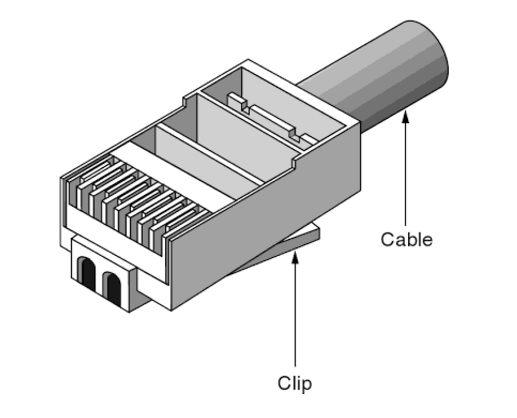
Insert the conductors into the plug. Hold the plug with the copper contacts facing up and the locking tab facing down. In this position, the orange/white conductor should be the first conductor on the left. Insert the conductors into the plug. Make sure the drain wire is wrapped around the jacket underneath the back of the plug prior to crimping in order to complete the ground.
Crimping the plug using the cable crimping tool. Place the plug into the crimp tool and squeeze handles tightly. The copper splicing tabs on the plug will pierce into each of the eight conductors. The locking tab will cinch onto the outer jacket of the cable.
Remove plug from tool. Check the conductor sequence and ensure outer jacket is inside the plug and secured by the locking tab. Trim excess drain wire just below entry into plug.
Repeat steps for other end of cable. Then use a cable tester to ensure proper installation and wiring of plugs.
Posted by: jowang at
02:59 AM
| Comments (1)
| Add Comment
Post contains 614 words, total size 5 kb.
February 13, 2017
The deployment of fiber optics in telecommunications and wide area networking has been common for many years, but more recently fiber optics have become increasingly prevalent in industrial data communications systems as well. Fiber optic technology uses pulses of light to carry data along strands of glass or plastic. It's the technology of choice for the government's National Broadband Network (NBN) and data centers, which promises to deliver next-generation 200G and 400G Ethernet speeds.

When talking about 'speed', we were actually talking about throughput (or capacity) — the amount of data you can transfer per unit time, says Associate Professor Robert Malaney from the University of New South Wales, School of Electrical Engineering and Telecommunications.
And fiber optics can definitely transfer more data at higher throughput over longer distances than copper wire. For example, a local area network using modern copper lines can carry 3000 telephone calls all at once, while a similar system using fiber optics can carry over 31,000.
So what gives it the technical edge over copper wires? Traditional copper wires transmit electrical currents, while fiber optic technology sends pulses of light generated by a light emitting diode or laser along optical fibers.
In both cases you're detecting changes in energy, and that's how you encode data. With copper wires you're looking at changes in the electromagnetic field, the intensity of that field and perhaps the phase of the wave being sent down a wire. With fiber optics, a transmitter converts electronic information into pulses of light — a pulse equates to a one, while no pulse is zero. When the signal reaches the other end, an optical receiver converts the light signal back into electronic information.
The throughput of the data is determined by the frequency range that a cable will carry — the higher the frequency range, the greater the bandwidth and the more data that can be put through per unit time. And this is the key difference — fiber optic cables have much higher bandwidths than copper cables (eg. cat5e copper cable).
"Optical fiber can carry much higher frequency ranges — note that light is a very high frequency signal — while copper wire attenuates or loses signal strength at higher frequencies," says Malaney.
Also, fiber optic technology is far less susceptible to noise and electromagnetic interference than electricity along a copper wire.
"You can send the signal for over 200 km without any real loss of quality while a copper cable signal suffers a lot of degradation over that distance," says Malaney.
As well as a significant increase in connection speed, fiber optic networks offer a tremendous capacity to keep up with any new technological advances. Once the basic fiber optic infrastructure is in place, it can be rearranged and the end point electronics upgraded when necessary, to deliver even higher capacity. It can do this far more effectively than existing wireless or copper based systems.
In terms of its serviceable lifetime, glass (from which fiber optic cable is made) is long lasting, stronger than copper and more able to retain its transmission properties after physical stress such as weight strain, or even attack by rats and cockatoos. We install fiber differently from copper: in good quality coatings, inside ducts, or in the case of newer systems, encased entirely by electrical transmission wires.
For applications where signal security is a concern, fiber optic technology is an excellent solution. Fiber optic cables do not generate electromagnetic fields that could be picked up by external sensors. It is also more difficult to 'steal' signals by spicing into optical fibers than it might be with conventional copper wiring.
Posted by: jowang at
08:48 AM
| Comments (1)
| Add Comment
Post contains 611 words, total size 5 kb.
February 06, 2017
Have you ever wired a cable directly into a piece of hardware? Some equipment in the past years provided terminals or termination blocks so that cable could be wired directly into a direct component. At the ends of the cables you install, something must provide access and transition for attachment to system electronics. Thus, you need connectors.
Connectors usually have a male component and a female one, except in the case of hermaphroditic connectors such as the IBM data connector. Jacks and plug are usually systematically shaped, but sometimes they are keyed, which means that they have a unique, asymmetric shape or some system of pins, tabs and slots that ensure that the plug can be inserted only one way in the jack. This article covers three types of connectors you may encounter when working with structured cabling system.
Many people in the cabling business use twisted-pair connectors more than any other type of connector. The connectors included the modular RJ types of jacks and plugs and the hermaphroditic connector employed by IBM that is used with shielded twisted-pair cabling (ie. cat6 shielded cable). What is equally important as the cable connector is the connector used with patch panels, punch-down blocks, and wall plates; this connector is called an IDC (insulation displacemeny connector).
Most unshielded twisted-pair (UTP) and screened twisted-pair (ScTP) cable installations use patch panels and, consequently, 110-style termination blocks. The 110-block contains rows of specially designed slots in which the cables are terminated using a punch-down tool.
Solid vs. Stranded Conductor CablesUTP and ScTP cables have either solid copper conductors or conductors made of several tiny strands of copper. Solid conductors are very stable geometrically and therefore electrically superior, but they will break if flexed very often. Stranded conductors are very flexible and resistant to bend-fatigue breaks, but their cross-sectional geometry changes as they are moved, and this can contribute to electrical anomalies. Stranded cables also have a higher attenuation than solid-conductor cables.
The differences in conductors mean a difference in IDC types. You have to be careful when purchasing plugs, wall plates, and patch panels because they won’t work interchangeably with solid- and stranded-core cables because the blade designs are different.
Twisted-pair cables are most commonly available as UTP, but occasionally, a customer or environmental circumstances may require that ScTP cable be installed. In an ScTP cable, the individual twisted pairs are not shielded, but all the pairs collectively have a thin shielded around the shielded of foil around them. Both UTP and ScTP cables use modular jacks and plugs. For decades, modular jacks have been commonplace in the home for telephone wiring.
Modular connectors come in four-, six-, and eight-position configurations. The number of positions defines the width of the connector. However, many times not all of the positions have metal contacts installed. Make sure that the connectors you purchase are properly populated with contacts for your application. Note the metal shield around the jack; it is designed to help reduce both EMI emissions and interference from outside sources, but it must be connected properly to the cable shield to be effective. The following figure shows an eight-position modular plug for UTP cable.
Shielded twisted-pair connectors go with the shielded twisted-pair cable which encases the signal-carrying wires in a conducting shield as a means of reducing the potential for electromagnetic interference. How effective the shielding is depends on the material used for the shield--its thickness and frequency, the type of electromagnetic noise field, the distance from the noise source to the shield, any shield discontinuity and the grounding practices. Please note that the crosstalk and signal noise can increase if the effects of the shield are not compensated for.
Posted by: jowang at
03:50 AM
| No Comments
| Add Comment
Post contains 627 words, total size 5 kb.
36 queries taking 0.1205 seconds, 78 records returned.
Powered by Minx 1.1.6c-pink.

