


July 29, 2016
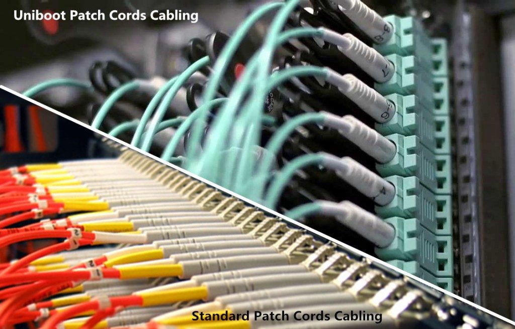
In the past years, to meet the growing bandwidth needs, data center technologies and cabling structures have changed a lot. High density apparently becomes the trend. Data center has to install more and more fiber optic jumper cables in a given space, which makes cable management a more and more difficult problem. New products and technologies are applied to achieve high density in data centers. To find an easy-to-manage and space-saving method for high density cabling becomes an urgent issue for data center managers. In this post, a favorable high density fiber cabling solution—LC uniboot fiber patch cable, which is born to solve problems during high density cabling, will be introduced.
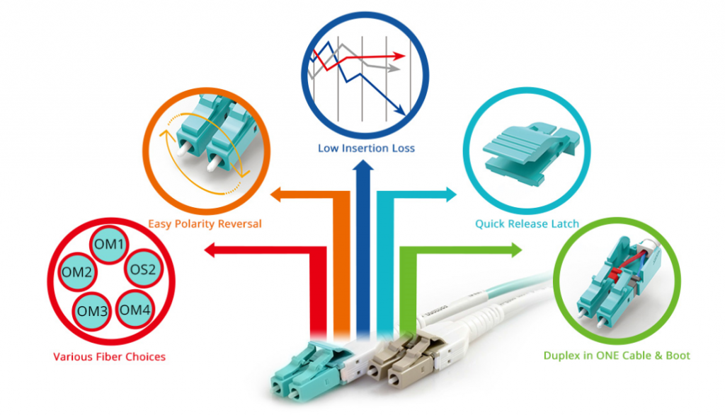
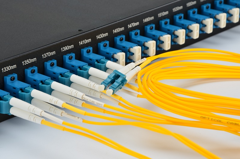
LC fiber optic connector can offer higher density and performance in many different environments compared to other types of fiber optic connectors, which makes it a more popular choice for many applications. That is why uniboot fiber patch cables terminated with specially designed LC fiber optic connectors have been invented. With its unique structure, LC uniboot fiber patch cable has more advantages over traditional LC to LC cable in high density cabling environments. Differences between LC uniboot fiber patch cables and standard LC fiber patch cables are noticeable. The following picture shows an LC uniboot fiber patch cable (left) and a standard LC fiber patch cable (right) separately.
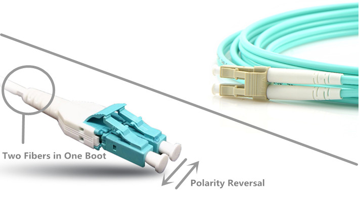
A traditional LC duplex fiber patch cable usually uses a two-cable design with two fibers separately enclosed in two different cables, and it is terminated on each end with a standard duplex LC fiber optic connector. LC uniboot fiber patch cable uses only one cable even it has two fibers. It has a single boot at the back of the duplex LC fiber optic connector. Two fibers for duplex transmission are firmly enclosed in a single cable, which can cut down the cable count up to 50% compared with traditional LC duplex fiber patch cords. Space requirements of data center cabling can be reduced significantly by LC uniboot fiber patch cables.
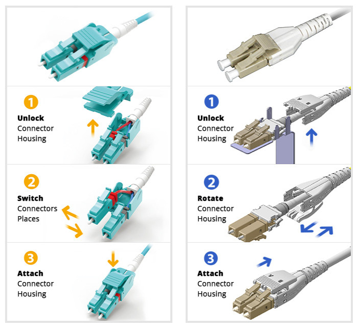
For LC duplex fiber patch cables, polarity change can be really inconvenient, especially in high density cabling environments like data centers. Additional tools and fiber cable re-termination are usually required to change polarity of traditional LC duplex fiber patch cables, which wastes both time and money. And sometimes, improper handling could result in various faults. But the polarity reversal for LC uniboot fiber patch cables is much easier, which can be easily changed by several simple steps without additional tools. Currently, there are several different versions of LC uniboot fiber patch cables, and the polarity reversals of them might differ from each other. Two commonly used versions of LC uniboot fiber patch cables polarity reversal steps are shown in the following picture.
With LC uniboot fiber patch cables, fiber optic network design can be more flexible without worrying about spaces and polarity problems. Other than space-saving and easy polarity reversal, LC uniboot fiber patch cable can also achieve more possibilities with its great features. Fiber optic cabling provides faster speeds with reliable quality, which saves a lot of time and money. And, the design and improvement of uniboot fiber patch cables have never stopped. LC uniboot fiber patch cable with push-plug tab has already been available in the market. This little change can make easier finger access and quicker latch release available, and it can also help to connect or disconnect a single fiber patch cable without affecting other surrounding links.
LC uniboot fiber patch cable can help solve problems in high density cable management with high efficiency. It is a more favorable solution compared to standard LC fiber patch cable. LC uniboot fiber patch cable can cut down fiber cabling spaces up to 50% and provide much easier polarity reversal solution. Different kinds of LC uniboot fiber patch cables are available for your applications, such as different cable lengths, different fibers and different cable jackets. You can choose the right one for your needs.
Posted by: jowang at
06:11 AM
| No Comments
| Add Comment
Post contains 693 words, total size 6 kb.
July 28, 2016
Nowadays, fiber optic cable becomes one of the most popular mediums for both new cabling installations and upgrades, including backbone, horizontal, and even desktop applications. Though fiber offers a number of advantages over copper, copper still has a space in telecommunication networks, for example, direct attach copper cables, like HP JG081C 10G SFP+ direct attach copper cable or Cisco QSFP+ breakout cable (Cisco QSFP-4SFP10G-CU5M). As one of the oldest types of cable ever invented, twisted pair cable was first developed in 1881. Since then, it has been widely deployed for telephone line networks. Nowadays, the application of twisted pair cables has been extended worldwide mainly for outdoor land lines offering telephone voice service.
Twisted pair cable is a kind of copper wiring made by putting two separate insulated wires together in a twisted pattern and running them parallel to each other. It is widely used in different kinds of data and voice infrastructures. To reduce crosstalk or electromagnetic induction between pairs of wires, two insulated copper wires are twisted around each other. Each connection on twisted pair requires both wires. Twisted pair can offset electromagnetic interference (EMI) from external sources to stop degrading the performance of circuit.

There are two twisted pair types: shielded and unshielded. A shielded twisted pair (STP) has a fine wire mesh surrounding the wires to protect the transmission; an unshielded twisted pair (UTP) does not. Shielded cable is used in older telephone networks, as well as network and data communications to reduce outside interference.
Also, different standards of twisted pair cables are specified into various categories as Cat 1, Cat 2, Cat 3, Cat 4, Cat 5/5e, Cat 6/6a, Cat 7/7a, Cat 8/8.1/8.2. And the following text will briefly introduce several categories.
Cat 5 twisted pair cable is often used for structured cabling of computer networks. It is available to 10/100 Mbps speeds at up to 100 MHz bandwidth. However, it is now considered to be obsolete and replaced by Cat 5e (enhanced). Cat 5e is one the most commonly used twisted pair cables now. The biggest distinction between Cat 5 and Cat 5e is that Cat 5e has a lower crosstalk and its transmitting speed can reach up to 1000 Mbps.
As a substitute of Cat 5/5e, Cat 6 twisted pair cable is applied to Gigabit Ethernet and other network physical layers. Cat 6 supports up to 10 Gbps speed at 250 MHz. When used for 10GBASE-T applications, Cat 6 has a reduced maximum length from 37 to 55 meters. Cat 6a (augmented) twisted pair cable has been evolved to perform at up to 500 MHz, thus the maximum cable distance is longer than Cat 6 of up to 100 meters.
Cat 7 is the standard for twisted pair cabling used for 1000BASE-T and 10GBASE-T networks. It provides performance of up to 600 MHz with a maximum length of 100 meters. Cat 7a (augmented) twisted pair cable has a higher frequency of 1000 MHz. Results show that Cat 7a may be possible to support 40 GbE or even 100 GbE at a very short length.
Cat 8 is the USA standard specified by ANSI/TIA while Cat 8.1 and Cat 8.2 are specified by ISO/IEC for global application. All these three kinds of Cat 8 twisted pair cables are used for 25GBASE-T and 40GBSE-T at the maximum frequency of up to 2 GHz. Except Cat 8 adopts Cat 8 links, Cat 8.1 uses class I links and Cat 8.2 uses class II links. The key difference between class I and class II is that class II allows three different styles of connectors that are not compatible with one another, or with the RJ45 connector.
Twisted pair cables have been classified into different grades called categories. Higher categories are more expensive than lower ones, but most of the cost is actually spent on labor force for installing the cables. And twisted pair cables under Cat 5 are not recommended now. Higher categories are the future trends for network cabling.
Posted by: jowang at
02:20 AM
| No Comments
| Add Comment
Post contains 683 words, total size 5 kb.
July 26, 2016
The deployment and termination of fiber optic cabling in data center usually cost a lot of time and labor. However, with the increasingly need for high density cabling in 40G/100G data centers, fiber cabling and termination become even more difficult and time-consuming if traditional field termination methods are still applied. And fiber optic networks are becoming more and more complex, which makes data center cabling becomes more difficult. Risks of faults caused by manual fiber termination will increase. To solve this problem and meet high density requirements of data centers, pre-termianted fiber cabling assemblies are introduced.
Pre-terminated fiber cabling is relatively a much easier way to install fiber optic cable. The connectors you specify are pre-terminated for you, and the fiber cable you specify is cut to the proper length that you need, such as LC to LC fiber patch cable, SC to LC cable, SC to ST fiber cable, or single mode patch cable, multimode patch cord. Deploying a data center by using field termination methods might need a few days or more. Engineers have to terminate a lot of fiber optic links and connect them to the right ports. To make sure there are no wrong links or bad fiber optic splicing joints, a lot of checking should be done.
However, pre-terminated fiber cable assemblies, using the plug-and-play designed modules and cables, can largely improve the working efficiency, increase cabling density and decrease the total data center installation cost. For example, multi-mode fiber networks for 40G/100G applications use parallel transmission with 8 or 20 fibers per link utilizing 12-fiber MTP/MPO connectors, making it harder to terminate than a single fiber connector. Instead, a pre-terminated MPO cable would be much easier. In addition, the factory terminated fiber cable assemblies eliminate the need of fiber optic splicing and provide higher performance compared with field terminated fiber optic cables.
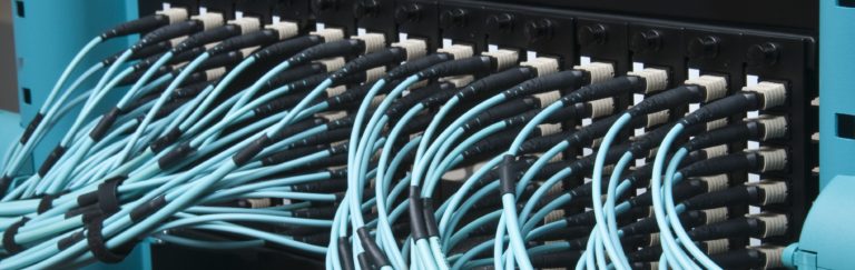
Commonly used pre-terminated fiber cabling assemblies for 40G/100G high density cabling applications are MTP/MPO fiber cable assemblies, including MTP/MPO trunk cable, MTP/MPO harness cable and MTP/MPO cassette. Making good use of these components can largely increase cabling density and working efficiency in data centers.
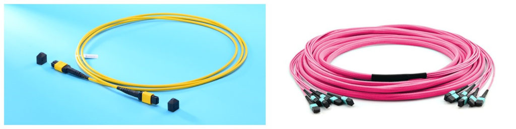
MTP/MPO trunk cable is a length of multi-fiber optical cable, which is usually used for backbone transmission in data center. 12-fiber MTP/MPO trunk cable and 24-fiber MTP/MPO trunk cable are commonly used for 40G and 100G applications separately. Generally, there are two versions of MTP/MPO trunk cable, single-strand MTP/MPO trunk cable and multi-strand MTP/MPO trunk cable. A multi-strand MTP/MPO trunk cable combines several single-stand MTP/MPO trunk cables together. For example, a 72-fiber MTP/MPO trunk cable has 6 strands of 12-fiber cables combining together and each strand is terminated with a 12-fiber MTP/MPO connector.
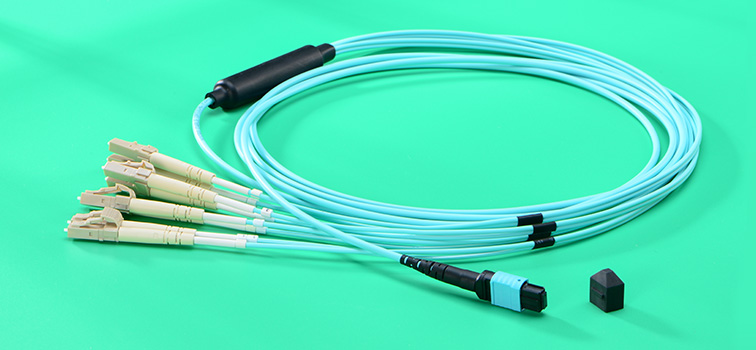
MTP/MPO harness cable is a fanout version of MTP/MPO optical cable. An MTP/MPO fiber optic connector is terminated on one end of the cable, and the fanout end is terminated with several other types of fiber optic connectors, which usually are LC fiber optic connectors. MTP/MPO harness cable is generally used for 40G to 10G transmission or 100G to 10G transmission. MTP/MPO harness cable also has various versions. The most commonly used types are 12-fiber MTP/MPO to 6 duplex LC harness cable for 40G duplex transmission and 24-fiber MTP/MPO to 12 duplex LC harness cable for 100G duplex transmission.
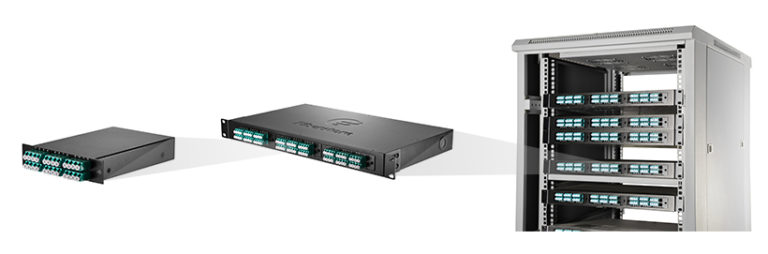
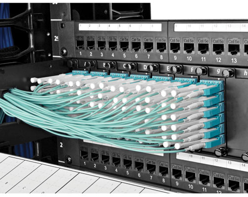
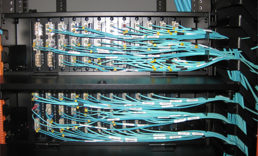
MTP/MPO cassette is a specially designed box which contains one or more small version of MTP harness cables inside it. Generally there is one MTP interface on the back rear of an MTP/MPO cassette and several LC interfaces on its front rear. It can be easily installed on the rack for easier cabling as shown in the following picture. In this way, the fiber optic connections are protected in this box and more fiber optic connections can be added to the data center without worrying about space limitation. The most commonly used are MTP/MPO LGX cassettes. However, driven by increasing need for high density, the size of MTP/MPO cassette gradually decreases. HD MTP/MPO cassette is also available in the market for higher cabling density.
Pre-terminated fiber cable assemblies help accelerate data center deployment, reduce costss and errors, and provide great flexibility and scalability. MTP/MPO cabling system as one of the most popular pre-terminated fiber cabling solutions can perfectly fit the 40G and 100G applications. The above mentioned products are just a really small part of the pre-terminated fiber cable assemblies.
Posted by: jowang at
07:01 AM
| No Comments
| Add Comment
Post contains 752 words, total size 7 kb.
July 22, 2016
10 Gigabit Ethernet (10GbE) now is a commonplace for current network backbones and data centers to support high-bandwidth applications. And with the continuous advancement and improvement in 10GbE technology, it has extended its applications to midmarket networks for the purpose of ensuring faster data transmission and better network performance. How to achieve an efficient and smooth 10GbE network? In this post, several connectivity options for 10GbE infrastructure will be introduced.
Nowadays, 10GbE has been an desirable and affordable choice with high performance. And there exists a distinct need for 10GbE networks. The ever-increasing applications require considerable bandwidth to support the transfer and streaming of large data, video and audio files. Besides, rapid and dramatical development of network technologies drive companies to upgrade their current infrastructure and improve its ability to keep pace with the developent. What's more, re-cabling a network can be money-consuming, thus organizations should take precautions to ensure that their cabling systems can perform well in the long run.
Why choose to deploy 10 Gigabit Ethernet? It has several advantages. First, 10 GbE provides the very best assurance for being able to support forthcoming technologies and delivers utmost investment protection. Second, 10 GbE is an ideal technology to move large amounts of data quickly. The bandwidth it provides in conjunction with server consolidation is highly advantageous for web caching, real-time application response, and parallel processing and storage. Moreover, 10GbE campus backbone establishment is a one-time expense that can provide significant cost savings when compared to monthly communications link bills. To implement 10GbE, here are several connectivity options for you.
Fiber cabling is typically used for remote campus connectivity, crowded wiring closets, long-distance communications and environments that need protection from interference, such as manufacturing areas. Fiber cabling is very reliable and less susceptible to attenuation, which makes it an optimum for sending data beyond 100 meters. However, fiber cabling is more costly than copper.
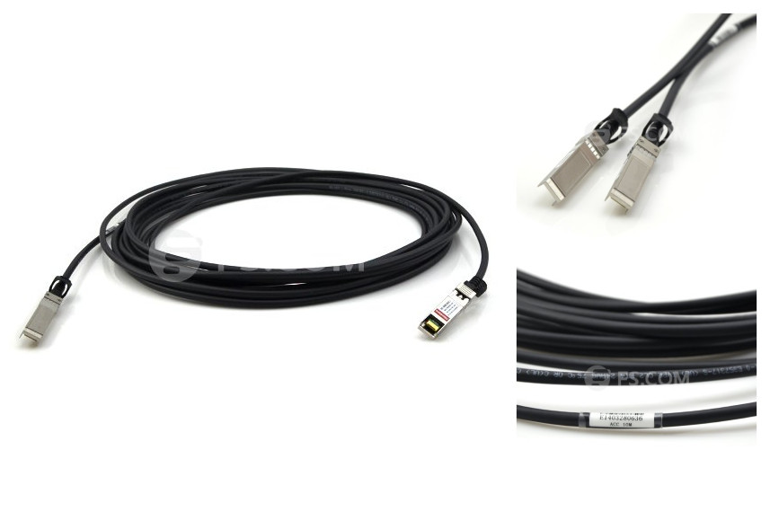
Copper cabling is popular for transmitting data between devices due to its low cost, easy installation and flexibility. Copper is best when utilized in short lengths, typically 100 meters or less. When employed over long distances, electromagnetic signal characteristics hinder performance. In addition, bundling copper cabling can cause interference, making it difficult to employ as a comprehensive backbone. Therefore, copper cabling has become the principal data carrying technique for communication among PCs and LANs, but long-distance transmission. 10G SFP+ direct attach copper cable, such as HP J9281B compatible SFP+ direct attach copper cable, as shown below, is a popular copper solution for 10 Gigabit Ethernet, which has become the main choice for servers and storage devices in a rack for its low latency, small connector and reasonable cost.
Other than the cabling choices, service providers should also pay much attention to the devices that connect their cabling to their networks. There are various transceiver modules available to match each gigabit standard. 10 GbE has four defined transceiver types.
SFP+: SFP+ transceiver, an extension of the SFP optical transceiver, is designed to increase the capacity of the existing SFP module. It has the same mechanical characteristics as the the SFP transceiver, just capable of supporting the higher speed. For many customers, the possibility of achieving 10G speeds and a mechanical form factor that allows 1G or 10G to reside in the same footprint, might prove attractive. It has now become the predominant 10G Ethernet connector type, and branded by many famous companies, like HP, Cisco, Finisar, etc.
XFP: XFP transceiver is the closest in size to the SFP pluggable transceiver now used for gigabit technology. It allows switch vendors to increase port density in a smaller area for cost savings. XFP transceiver cannot support the current 802.3ak copper or the 10GBASE-LX4 standards.
X2: X2 transceiver is about 2/3 the size of XENPAK module. With the same "hot pluggable" specifications and supporting all the 10GbE standards (including copper), the X2 form factor allows for more port density on switches. X2 provides customers with a strong sense of assurance that this technology is the best choice for today and will have strong vendor support.
XENPAK: XENPAK transceiver is the first 10GbE pluggable transceiver on the market to support the 802.3ae standard transmission optics. They are large, bulky and used mainly in LAN switches. These transceivers are "hot pluggable" and support the new 802.3ak copper standard with vendors now producing transceivers to connect CX4 cables.
10 Gigabit Ethernet is commonly used to upgrade networks and support bandwidth-intensive applications. Companies and organizations should have a solid and comprehensive understanding of 10GbE technology before deploying it, which would help to develop a sound migration and cabling method and surely get benefits from 10 Gigabit Ethernet in the long run.
Posted by: jowang at
07:36 AM
| No Comments
| Add Comment
Post contains 802 words, total size 6 kb.
July 21, 2016
Fiber optic cables have been more and more widely used in all kinds of applications. You can use fiber optic jumper cables to connect end devices or network hardware to the structured cabling system and one popular type of fiber optic jumper cables, MPO cable, is a good solution for your high density applications. The technique to handle optical fiber can have a significant impact on the functionality and reliability of a fiber optic cable. The cost of rework or replacement due to improper handling can also be significant and may cause monetary losses and increased processing times. In this post, several suggestions will be given for proper handling of optical fiber during the design and implementation of a fiber handling program specific to a user's application and manufacturing process.
Before illustrating the suggestions for proper handling of optical fibers, a few kinds of fiber damage will be introduced, which are compressive damage, abrasive damage, fatigue damage and particulate penetration.
Compressive damage may occur when a fiber is pinched, clamped, or constrained to a point where the coating or glass layers become damaged. This can result in several effects depending on the severity of the compressive force, including coating delamination, coating damage (splits, cracks), and strength degradation due to the introduction of flaws onto the glass surface.
Abrasive damage may occur when a fiber comes into sliding contact with a sharp object such that it is scratched or scraped. This may result in damage of the polymeric coating or removal of it from the fiber. And it is also probably that the contact will damage the glass surface of the fiber, creating flaws that reduce the fiber's strength.
Fatigue damage is defined as the slow extension of a flaw over time due to the application of a tensile stress in the presence of moisture or humidity. The implication of fatigue is that a fiber may degrade in strength over time if placed under a considerable stress, which could be in form of a pure tensile, bending, or torsional stress, or any combination thereof.
Particulate penetration occurs when a hard particle, such as glass or ceramic, penetrates the coating layer of a fiber. This can often be initiated due to poor process cleanliness, and exacerbated by static electricity and subsequent processing.
To avoid those four kinds of fiber damages mentioned above as much as possible, there are corresponding practices.
- Never place tools, fixtures, or components on top of an optical fiber.
- Do not over-tighten objects used to constrain optical fiber.
- Avoid the use of tweezers or other such tools to handle optical fiber.
- Never allow a fiber to contact an uncontrolled surface where it may be stepped upon, rolled over with a chair castor, etc.
- If fiber is clamped during processing, ensure that the clamping pressure is limited so that damage is not induced. Any clamping materials that physically contact the fiber should be smooth, pliable and nonabrasive.
- Do not allow optical fiber to contact sharp or jagged edges or work surfaces.
- Take care with fingernails and jewelry when handling optical fiber.
- Never wipe an optical fiber with an abrasive material or with organic solvents such as acetone.
- Never allow an optical fiber to contact an uncontrolled surface where it may become snagged or otherwise abraded.
- Regularly check any pulleys or other hardware that the fiber may contact for nicks, burrs, corrosion, etc. All surfaces should be smooth and free of any debris or defect.
Always follow the recommended applied stress design guidelines for optical fiber. Generally, these rules dictate that an optical fiber should not be subjected to a stress higher than one-half the proof stress for a time on the order of one second, and to no more than one-third the proof stress for a time on the order of four hours.
- Clean all surfaces that contact the optical fiber regularly.
- Ensure that any bins or receptacles used to hold or contain fiber are free of debris.
- Never allow an optical fiber to contact an uncontrolled or dirty surface where it may contact particulate material.
- Check pulleys, work surfaces and other hardware regularly for the presence of corrosion or other contamination.
- Control static electricity, which may reduce fiber tangles, as well as attraction of particulate to the fiber.
- Do not cut or break optical fibers directly over work surfaces, which creates high stress fracture and may release numerous microscopic shards of glass over the work surface.
Proper handling of optical fiber can help you save a lot of money. These suggestions to reduce occurrences of fiber damage or breakage are applicable to a wide range of processes and applications. To create a functional and reliable product utilizing optical fiber, you can follow these guidelines in your handling and processing procedures.
Posted by: jowang at
08:01 AM
| No Comments
| Add Comment
Post contains 822 words, total size 7 kb.
July 17, 2016
Nowadays, 10 Gigabit Ethernet network has been very popular and been employed by large amount of enterprises in their corporate backbones, data centers, and server farms to support high-bandwidth applications. To achieve a reliable and cost-effective 10 Gigabit Ethernet network, here are several factors that you should take into consideration for the deployment.
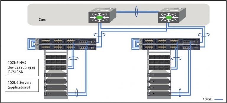
Direct-attached storage, network attached storage and SAN are three types of storage in a network. Among them, SAN is the most flexible and scalable solution for data center and high-density applications. But SAN costs much and needs special training for the installation and maintainance of the Fibre Channel interconnect fabric. The internet small computer system interface (iSCSI), which allows 10GbE infrastructure to be used as a SAN fabric, makes 10 GbE an attractive interconnect fabric for SAN applications. Compared with Fibre Channel, 10GbE infrastructure is more favorable because it can reduce equipment and management costs, enhance server management, improve disaster recovery and deliver excellent performance.
Many organizations try to optimize their data centers by seeking server virtualization, which can support several applications and operating systems on a single server by defining multiple virtual machines on the server. And this can help organizations to reduce server inventory, better utilize servers, and mange resources more efficiently. Server virtualization relies heavily on networking and storage. Virtual machines require lot of storage. The network connectivity between servers and storage must be fast enough to avoid bottlenecks. 10GbE can provide fast connectivity for virtualized environments.
Today, traffic at the edge of the network has increased dramatically. Gigabit Ethernet to the desktop has become more popular. Many people adopt Gigabit Ethernet to the desktop, increasing the oversubscription ratios of the rest of the network, which brings the bottleneck between large amounts of Gigabit traffic at the edge of the network and the aggregation layer or core. 10 GbE allows the aggregation layer to scale to meet the increasing demands of users and applications. It can well solve the bottleneck for its three advantages: 10 GbE link uses fewer fiber stands compared with Gigabit Ethernet aggregation, 10 GbE can support multi-gigabit streams and 10 GbE provides greater scalability, bringing a future-proof network.
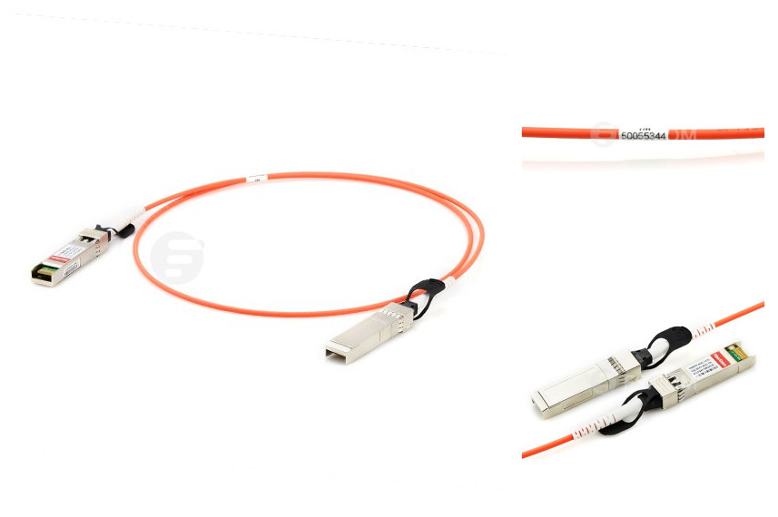
To accomplish 10 GbE network deployment, three important factors should be considered, the type of fiber cable (MMF of MF), the type of 10 GbE physical interface and optics module (XENPAK, X2, XFP and SFP+). Form factor options are interoperable when 10 GbE physical interface type is the same on both ends of the fiber link. For example, 10GBASE-SR XFP on the left can be linked with one 10GBASE-SR SFP+ on the right. But 10GBASE-SR SFP+ can't connect to one 10GBASE-LRM SFP+ at the other end of the link. And 10G SFP+ active optical cable, such as Cisco SFP-10G-AOC3M SFP+ active optical cable (as shown below) and Cisco SFP+ active optical cable, SFP-10G-AOC10M, is also a good choice.
Other than fiber optic cabling solutions, there are also copper cabling solutions for 10GbE. Copper cabling solutions are suitable for short distance connections. There are three copper cabling solutions: 10GBASE-CX4, SFP+ direct attach copper cable and 10GBASE-T.
10GBASE-CX4 is the first 10 GbE standard. It's economical and it allows very low latency, but it's a too large form factor for high density port counts in aggregation switches. 10G SFP+ direct attach copper cable (10g copper SFP) is a popular copper solution for 10 Gigabit Ethernet, which has become the main choice for servers and storage devices in a rack for its low latency, small connector and reasonable cost. 10GBASE-T runs 10 GbE over Cat6a and Cat7 up to 100 m.
A top-of-rack (ToR) switch is a switch with a low number of ports that sits at the very top or in the middle of a 19" telco rack in data centers. A ToR switch provides a simple and low-cost way to easily add more capacity to a network. It connects several servers and other network components together in a single rack. ToR switch uses SFP+ to provide 10G network in an efficient 1U form factor. Each server and network storage device can be directly connected to the ToR switch, eliminating the need for intermediate patch panels. And the cabling outside the rack, the ToR switch uplink connection to the aggregation layer, simplifies moving racks. The figure below shows a 10GbE ToR switching solution for servers and network storage. Because the servers are virtualized, so the active-active server team can be distributed across two stacked witches, which can ensure physical redundancy for the servers while connected to the same logical switch. What's more, failover protection can be offered if one physical link goes down.
10 Gigabit Ethernet network is not the fastest solution, but it is quite enough for common applications in our daily life. For a better and successful 10 Gigabit Ethernet network deployment, you need to take all those factors mentioned above into consideration. And it can also help you make better options about fiber or copper cabling solutions for your 10G networks.
Posted by: jowang at
03:22 AM
| No Comments
| Add Comment
Post contains 866 words, total size 7 kb.
July 15, 2016
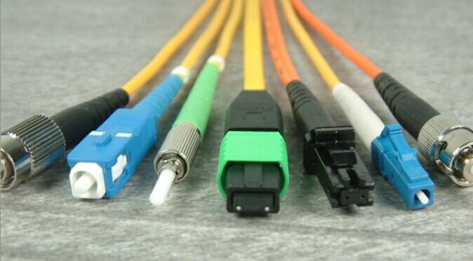
There are many kinds of fiber optic connectors, such as LC, ST, SC, FC, MPO, MTRJ, etc. LC connector is one of the most commonly used connector type. Fiber optic jumper cables can be terminated with LC connectors on one end or both ends, like SC to LC cable, LC to ST fiber patch cable or LC to LC fiber patch cable. And there are LC to LC multimode simplex fiber optic patch cableand LC to LC multimode duplex fiber optic patch cable, for LC connector can be both simplex and duplex. LC duplex connector, the most well-known representative of SFF (small form factor) connectors, is widely adopted in fiber optic connectivity of today's LANs (Local Area Networks) and data center cabling. How much do you know about it? This blog will guide you to the world of LC duplex connector.
The standard LC connector, namely the traditional type, was developed by Lucent Technologies. It is designed with a retaining tab mechanism that is similar to the RJ45 connector. The body of a standard LC connector is a squarish shape, which is similar to an SC connector. Thus, LC connector is also called mini SC connector. Standard LC duplex connector is LC connector in a duplex configuration with a plastic clip. The ferrule of an LC connector is 1.25 mm. As the basic type, standard LC duplex connectors are universal in various fiber optic network applications.
The LC duplex uniboot connector is two LC connectors encased in a common housing with one boot, terminated on a single twin-fiber round cable. This type of connector LC duplex connector is more compact compared to standard LC duplex connector. Fiber patch cables terminated with uniboot LC duplex connectors are ideal for high-density cabling applications, for they greatly reduce fiber counts and cable management space. And you need to know that the boots of an LC duplex connector can be configured with various versions according to different requirements. In addition to standard connector boots and uniboots, there are mini boots, BTW (Behind the Wall) boots, short boots, and 45 or 90 degree angel boots in the market.
If you have ever released LC duplex connectors from patch panels in high-density cablings, you might know how difficult it can be. In a high-density cabling, thumbs and forefingers have hard access to pulling connectors. LC-HD duplex connectors are ideal solution to this issue. With a flexible "pull-tab" or "push-pull tab", the LC-HD duplex connector can be disengaged easily from densely loaded panels without using special tools, which gives users easy accessibility in tight areas of high-density data center applications. And LC-HD duplex connectors with the uniboot design are more suitable to high-density cabling applications.
The mini-LC duplex connector is a variation of standard LC connector. It uses current industry-standard LC connectors but allows closer ferrule spacing by adopting the duplex clip (usually with color coding). Mini-LC duplex connector has a reduced center spacing of 5.25 mm compared to a standard LC duplex connector of 6.25 mm. This type of LC duplex connector is designed to operate with the Mini SFP modules and provides a higher density deployment for data center equipment.
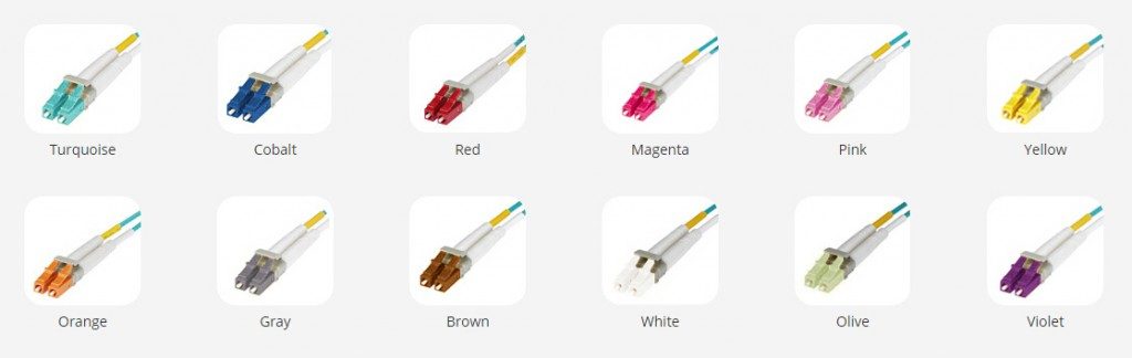
Keyed LC duplex connector assemblies add more colors to the LC connector world as they use 12 color-coded keyed designs. Each color of keyed LC duplex connectors represents a unique keyed pattern. And each keyed design only allows its matched color-coded adapter to be mated. Keyed LC duplex connector can help to segregate or identify parts or paths within a network infrastructure, as well as to reduce the risk of accidental or malicious network access, particularly in shared access areas or in secure hierarchical environments.
There are many kinds of LC duplex connectors and, with the increasing requirements and the development of technology, there will be more new members to join the family. To choose the ideal type of LC duplex connector for your applications among all those types of LC duplex connectors, all you need to do is get a better understanding about them before making a decision.
Posted by: jowang at
02:18 AM
| No Comments
| Add Comment
Post contains 702 words, total size 6 kb.
July 13, 2016
When talking about fiber optic jumper cables, such as LC LC multimode duplex fiber cable or LC SC single-mode simplex fiber optic patch cable, we came across simplex and duplex, or full duplex. What are simplex and full duplex? They are two kinds of communication channels in telecommunications and computer networking, which provide pathways to convey information. In fact, other than simplex and full duplex, there is another communication channel named half duplex. These three communication channels are commonly used in telecommunication networks.
A communication channel can be either a physical transmission medium or a logical connection over a multiplexed medium. The physical transmission medium refers to the material substance that can propagate energy waves, such as wires in data communication. And the logical connection usually refers to the circuit switched connection or packet-mode virtual circuit connection, such as a radio channel. With communication channels, information can be transmitted without obstruction. In this article, a brief introduction to these three communication channel types will be given.
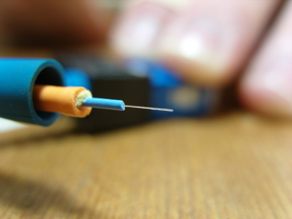
A simplex communication channel only sends information in one direction. For example, a radio station usually sends signals to the audience but never receives signals from them, thus a radio station uses a simplex channel. And it is also commonly used in fiber optic communication. One strand is used for transmitting signals or for receiving signals. The good part of simplex mode is that its entire bandwidth can be used during the transmission.
![]()
In half duplex mode, data can be transmitted in both directions on a signal carrier but not at the same time. At a certain point, it is actually a simplex channel whose transmission direction can be switched. Walkie-talkie is a typical half duplex device. It has a "push-to-talk" button which can be used to turn on the transmitter but turn off the receiver. Therefore, once you push the button, you cannot hear the person you are talking to but your partner can hear you. An advantage of half-duplex is that the single track is cheaper than the double tracks.
A full duplex communication channel is able to transmit and receive data in both directions on a signal carrier at the same time. It is constructed by a pair of simplex links that allows bidirectional simultaneous transmission. Take telephone as an example, people at both ends of a call can speak and be heard by each other at the same time because there are two communication paths between them. Thus, using the full duplex mode can greatly increase the efficiency of communication.

A simplex fiber optic cable has only one strand of tight-buffered fiber inside the cable jacket for one-way data transmission. The aramid yarn and protective jacket enable the cable to be connected and crimped to a mechanical connector. It can be used for both multimode and single mode patch cable. For instance, single-mode simplex fiber optic cable is suitable for networks that require data to be transmitted in one direction over long distance. Different from simplex fiber optic cable, duplex fiber optic cable has two strands of fibers constructed in a zipcord style. It is often used for duplex communication between devices to transmit and receive signals simultaneously. Duplex fiber optic cable can be applied to all sorts of applications, such as workstations, fiber switches and servers, fiber modems and so on. And single-mode or multimode cable is also available with duplex cables.
To understand the operation of networking, you should at least know the concept of communication channels. Simplex, half duplex and full duplex are three modes of communication channels. Each one can be deployed for different applications. To make a cost-effective decision, you can choose the right fiber optic cable according to the channel mode that you need.
Posted by: jowang at
02:31 AM
| No Comments
| Add Comment
Post contains 643 words, total size 5 kb.
July 11, 2016
Cisco GLC-SX-MMD transceiver is a 1000BASE-SX SFP optical transceiver. This hot-swappable input/output device plugs into a Gigabit Ethernet port or slot and allows the port to be linked with the network via multimode optical fiber. Cisco GLC-SX-MMD transceiver is a replacement of Cisco GLC-SX-MM transceiver. The module numbers of these two SFP transceivers differ only in one letter "D". This "D" mainly represents a function named DDM, which is inherited by many fiber optic transceivers offered today. What is this DDM function? Why this DDM function can offer GLC-SX-MMD transceiver advantages over GLC-SX-MM transceiver? This article will help you understand DDM.
DDM is short for digital diagnostic monitoring according to the industry standard MSA (Multi-Source Agreement) SFF-8472 and is also known as DOM (digital optical monitoring). When selecting fiber optic transceivers today, you can choose transceiver modules with or without DDM/DOM function. Most of fiber optic transceivers now are with the DDM function. This technology allows the user to monitor real-time parameters of the fiber optic transceivers, like optical input/output power, temperature, laser bias current, and transceiver supply voltage, and so on.
DDM can provide component monitoring on transceiver applications in details. The SFF-8472 added DDM interface and outlined that DDM interface is an extension of the serial ID interface defined in GBIC specification, as well as the SFP MSA. DDM interface includes a system of alarm and warning flags which alert the host system when particular operating parameters are outside of a factory set normal operating. Thus, DDM interface can also enable the end user with the capabilities of fault isolation and failure prediction. This part will explain what can be done with DDM.
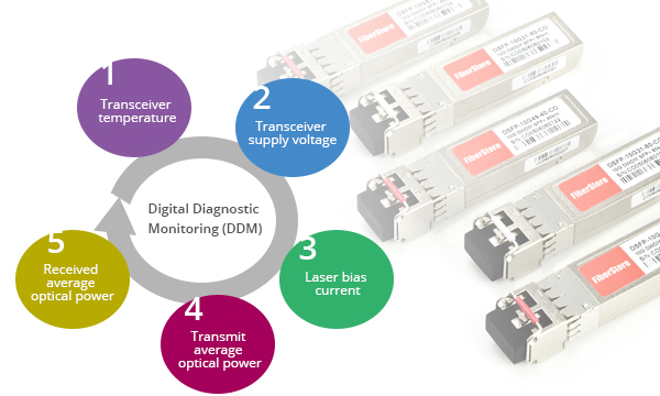
Component Monitoring: DDM enables the end user to monitor key parameters in the performance of fiber optic transceivers. The real-time diagnostic parameters can be monitored to alert the system when the transceiver's specified operating limits are exceeded and compliance cannot be ensured. These key parameters includes:
- Transceiver temperature
- Transceiver supply voltage
- Laser bias current
- Transmit average optical power
- Received optical modulation amplitude (OMA) or Average Optical Power
Fault Isolation: DDM function can be used to isolate the particular location of fault in fiber optic network systems. Combining the DDM interface status flags, transceiver hard pins and diagnostic parametric monitor data the specific location and cause of a link failure can be pinpointed.
Failure Prediction: DDM can also be used to help predict failure on fiber optic links, which is based on the transceiver parametric performance. Although, this application is not yet fully mature, but there is still room for improvement. There are two basic types of failure conditions that can be seen on fiber optic transceivers. One is device faults, which means non-operation or malfunction of a device and is typically applied to transmitter performance, due to nature of semiconductor lasers. The other is high error rate conditions, which means operating conditions are such that a fiber optic transceiver is operating at its signal-to-noise limit, and is applied more to fiber optic receiver performance.
Providing parameter monitoring, fault isolation, and failure prediction, fiber optic transceivers with DDM help to ensure that the business can be proactive in preventative maintenance of the network and ensure business continuity. So it would be easy to explain why modern transceivers are with DDM and why GLC-SX-MMD SFP optical transceiver can replace GLC-SX-MM SFP optical transceiver. It is an irresistible trend of industry and technology development. Although fiber optic transceivers with DDM function are much more popular than those without DDM, some users still choose the older optical transceivers in consideration of the upgrading costs.
Posted by: jowang at
07:56 AM
| No Comments
| Add Comment
Post contains 608 words, total size 5 kb.
July 09, 2016
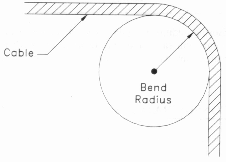
When you install fiber optic jumper cables, you should not bend them beyond their bend radius, for light may "leak out" when the fiber is bent. To install fiber optic jumper cables in tight spaces of high-density fiber patching areas in data centers, more cable bending are inevitably needed. As the fiber bends more acutely, more light leaks out (shown in the picture below). How to solve this problem? The answer is bend insensitive fiber patch cable. Bend insensitive fiber patch cable exhibits much lower optical power loss under bend conditions while remaining compatible with conventional cabling. What is bend insensitive fiber patch cable? This post will talk about this solution.

To understand bend insensitive fiber patch cable, first you need to what bend radius is. Bend radius is the minimum radius one can bend a pipe, tube, sheet, cable or hose without kinking it, damaging it, or shortening its life. The smaller the bend radius is, the greater is the material flexibility. When installing fiber optic jumper cables, you need to be careful enough not to exceed the cable bend radius. Usually, if no specific recommendations are available from the cable manufacturer, the cable bend radius should be 20 times smaller than the cable's outside diameter when pulling the cable and 10 times the outside diameter when lashed in place. For example, while pulling a 2mm diameter cable, only a 40mm sweep is allowed; when lashed in place, make sure it's a 20mm sweep. For most of today's fiber patch cables, the bend radius is 30 mm. As we know, there are single-mode patch cable and multimode patch cord, and accordingly there are single-mode bend insensitive fiber patch cables and multimode bend insensitive fiber patch cables. These two kinds of bend insensitive fiber patch cables will be introduced below.
Single-mode bend insensitive fiber patch cables have been commercially available for a few years. ITU recommendation G.657 specifies two classes of single-mode bend insensitive fiber patch cables: G.657 A and G.657 B. Each category (A and B) is then divided into two sub-categories: G.657.A1, G.657.A2 and G.657.B1, G.657.B2. The minimum bend radius of G.657.A1 fibers is 10 mm, G.657.A2 and G.657.B1 fibers is 7.5 mm and G.657.B2 fibers is 5 mm. G.657.A1 and G.657.A2 fibers are fully compliant with ITU-T G.652.D fibers. Compared with minimum bend radius of the standard single-mode G.652 fibers, which is usually 30 mm, G.657 single-mode bend insensitive fiber patch cables are much more flexible, which thus can be confidently installed with a variety of installation methods and in the increasingly high-density application spaces of today's data center.
Multimode bend insensitive fiber patch cables with a minimum bend radius of 7.5mm compares very favorably to the 30mm bend radius traditionally specified. To achieve this, an optical "trench" is added to the cladding area outside of the fiber core. This trench retains most of the light that would have escaped the core of a traditional multimode fiber. Requirements for a tighter bend radius have been developed based primarily on factors in the FTTH (fiber to the home) market. However, the benefits for premise markets have rapidly become apparent, particularly in data centers where more and more fibers are being installed in smaller areas. The expectation is that this new feature can enable deployment of multimode fibers in higher densities.
Bend insensitive fiber patch cables are made with solid trench which assists fiber optic cable to reduce optical loss when the cable is bent. They provide the same high quality, mechanical features and optical performance as standard fiber patch cords with the added capability of maintaining optical performance when bent or flexed. Bend insensitive fiber patch cables are available for multimode (OM2, OM3 and OM4) and single-mode (OS2) networks. Whether to choose single-mode bend insensitive fiber patch cables or multimode bend insensitive fiber patch cables, you can make a decision based on your applications.
Posted by: jowang at
01:47 AM
| No Comments
| Add Comment
Post contains 669 words, total size 6 kb.
July 07, 2016
As we know, direct attach cable assemblies are mainly used as media to support high transfer rates between servers, switches and storage devices in data centers. They use the same port as optical transceivers. With significant cost savings and power savings in short reach applications, direct attach cable assemblies are becoming more and more popular among data center operators. In this post, we will talk about direct attach cable solutions for data center interconnection.
Direct attach cable assemblies are terminated with transceiver-style plugs, such as SFP+ (enhanced small form-factor pluggable), SFP28, QSFP+ (quad small form-factor pluggable), QSFP28, and CXP, etc. Using the same port as transceiver optics, direct attach cables can support Ethernet, Infiniband and Fibre Channel but with independent protocols. In general, direct attach cable assemblies are divided into three families—direct attach passive copper cable, direct attach active copper cable and active optical cable (AOC).
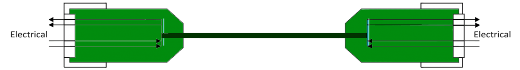
Passive direct attach copper cables are without active circuitry component. They can achieve interconnections up to 7m at 10 Gbps or 40 Gbps with low power. Direct attach passive copper cable assemblies, like HP J9281B SFP+ passive direct attach copper cable, offer high-speed connectivity between equipment. They are compatible with hubs, switches, routers, servers, and network interface cards (NICs) from leading electronics manufacturers like Cisco, Juniper, etc.
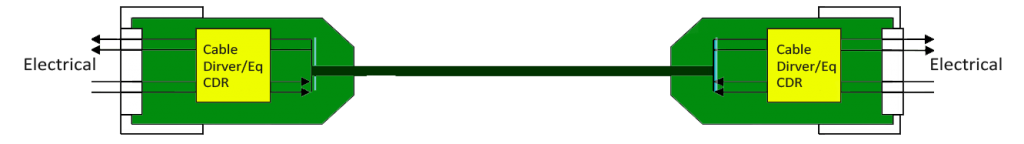
Active copper cables are designed in the same cable type as the passive one, but they contain low power circuitry in the connector to boost the signal and are driven from the port without additional power requirements. The active version provides a low cost alternative to optical transceivers, and are generally used for end of row or middle of row data center architectures for interconnect distances of up to 15 meters.
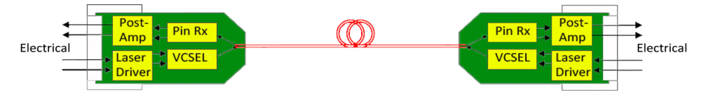
Active optical cable (AOC) incorporates active electrical and optical components. It can achieve longer distance than the copper assemblies. In general, active optical cable can reach more than 100m via multimode fiber. Compared to direct attach copper cable, AOC, like Cisco SFP-10G-AOC10M SFP+ AOC, weighs less and can support longer transmission distance. It is immune to electromagnetic energy since the optical fiber is dielectric (not able to conduct electric current). And it is an alternative to optical transceivers and it can eliminate the separable interface between transceiver module and optical cable. However, it costs more than copper cable.
In addition, with the fan-out technology, both direct attach copper cable and active optical cable can be designed as breakout direct attach cable assemblies, like 40G QSFP+ to 4x10G SFP+ AOC, which can better satisfy the demands on network migration.
Direct attach cable assemblies are ideal choices for short-reach direct connection applications. Generally, they are used in the EDA (Equipment Distribution Area) where cabinets and racks house end equipment (servers) and where horizontal cabling from the HDA (Horizontal Distribution Area) are terminated at patch panels, as shown in the following picture:
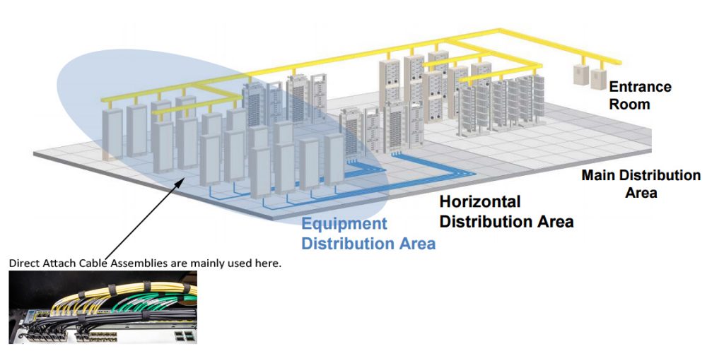
For interconnection in racks and between rows of racks, direct attach cable assemblies are used to connect server to switch, storage to switch or switch to switch. Depending on different interconnect applications and distance requirements, direct attach copper cables, passive or active, active optical cable, or breakout direct attach cable assemblies with various length options can be used.
As 10G network is widely deployed in today's data center, 10G SFP+ DACs are commonly used in interconnect applications below 15m, such as server to switch or storage to switch interconnection in the same rack. And now 25GbE is popular and 25G direct attach cable assemblies, such as SFP28 DACs, are already available in the market. For 40GbE, 40G QSFP+ DACs and AOCs are used. Of course, higher speed and more bandwidth are needed for spine switches. Thus, 100G DACs, like QSFP28 DACs are used in this case.
There are various direct attach cables, including direct attach copper cable assemblies and active optical cable assemblies. They can cover data rates of 10G, 25G, 40G, and 100G. You can choose SFP+ direct attach cables for your 10G networks, or QSFP+ direct attach cables for your 40G networks. And both copper and optical fiber options are available. You need to know more about them first and then make the right choice.
Posted by: jowang at
02:43 AM
| No Comments
| Add Comment
Post contains 724 words, total size 6 kb.
July 04, 2016
As we know, fiber optic jumper cables are designed to interconnect or cross connect fiber networks within structured cabling systems. One common application of fiber optic jumper cables is in data centers to interconnect ports and transceivers that accept LC and MPO/MTP fiber optic connectors. There are a full range of cost-effective fiber optic patch cable solutions which can meet your demands now and even for your upgrades in the future. In this post, we will demonstrate the high-speed fiber patch cable solutions for 10G, 40G, and 100G Ethernet transceiver ports interconnection.
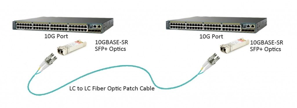
Today's data centers are still primarily architected around 10 Gigabit Ethernet (GbE). After almost ten years of revolution, SFP+ optical transceiver gradually becomes the main stream of 10G transceiver in data center optics market. According to the optical ports of SFP+ form factor, LC duplex fiber patch cable is required to complete the link between two SFP+ transceiver modules which are plugged into switches, routers or server NICs (Network Interface Cards), as shown in the following picture. High quality standard LC duplex patch cables are available in both single-mode and multimode versions, which are LC LC single-mode duplex fiber cable and LC LC multimode duplex fiber cable. With a wide range of material options, they can meet any working environment.
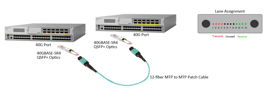
In recent several years, 40 GbE has gained more popularity and the market of 40GbE is encouraging. As data centers tend to deploy 40G Ethernet, 40G transceivers are ramping up. QSFP+ (quad small form-factor pluggable plus), as the most popular form factor for 40 GbE, has been widely used in data center switching fabrics. For the short reach interconnection between two QSFP+ optical transceiver ports, each QSFP+ module requires an MPO/MTP connection, as shown in the following picture. MTP to MTP (or MPO to MPO) assemblies can also be in single-mode or multimode versions, with jacket ratings of riser, plenum or LSZH. Users can easily upgrade their networks to future 40/100G applications with popular multimode OM3 and OM4 cable assemblies. Note: For single-mode 40G QSFP+ interconnection, duplex LC single-mode patch cable is commonly used; but for 40GBASE-PLRL4 QSFP+ interconnection, a 12-fiber MPO/MTP single-mode cable is needed.
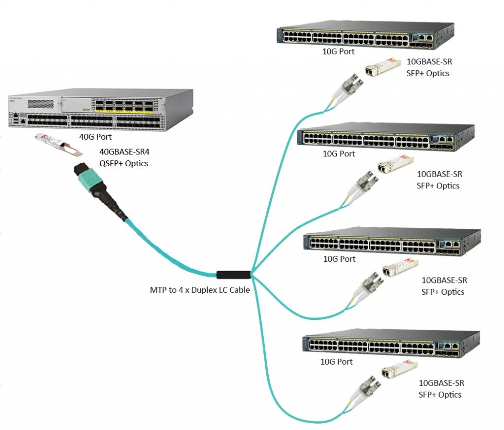
Other than the QSFP+ to QSFP+ connection, a single QSFP+ port (4 x 10 Gbps) can also breakout to four SFP+ ports, which is another interconnected solution for 40G transceiver. Using an MPO/MTP to LC assemblies, as shown in the following picture, can easily achieve the migration of 10G to 40G.
As the increasing bandwidth requirements of private and public cloud data centers and communication service providers, 100GbE has been growing rapidly and 2016 is considered as the year of 100G. Various 100G transceivers, such as CXP, CFP, CFP2, CFP4 and QSFP28 are available for different applications requiring data rates of 100G.
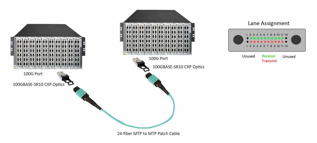
24-fiber MPO/MTP assemblies, implemented with 10 lanes of 10 Gbps, are ideal for 100GBASE-SR10 CXP/CFP to CXP/CFP interconnection in data center. Among the 24 fibers, only 20 fibers in the middle of the connector are used to transmit and receive signals at 10 Gbps and the 2 top and bottom fibers are unused. The picture below shows the interconnection between two 100GBASE-SR10 CXP ports.
QSFP28 optical transceiver has the exact same footprint as the 40G QSFP+ module, but QSFP28 is implemented with four 25Gbps lanes. To interconnect a multimode QSFP28 link, a 12-fiber MPO/MTP patch cable is required, but for a single-mode link (100GBASE-LR4 QSFP2![]() , a duplex LC single-mode patch cable is required. The interconnection of QSFP28 multimode link is similar with the case of 40GBASE-SR4 QSFP+.
, a duplex LC single-mode patch cable is required. The interconnection of QSFP28 multimode link is similar with the case of 40GBASE-SR4 QSFP+.
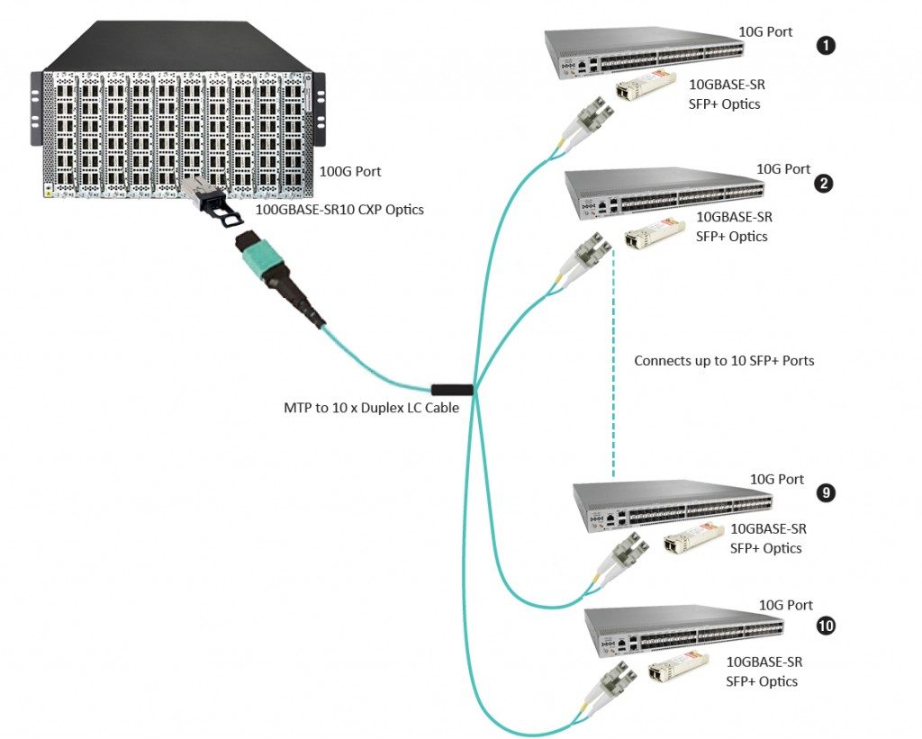
As mentioned above, 100GBASE-SR10 CXP/CFP module uses ten 10Gbps lanes to achieve 100Gbps data rate. Thus, a CXP/CFP port can be breakout to ten SFP+ ports using a 24-fiber MTP to LC harness cables, as shown in the following picture.
High-speed fiber patch cables are required for modern data centers. Different high-speed fiber patch cable solutions are available for your 10G, 40G, and 100G Ethernet transceiver ports interconnection. You can make the appropriate choices based on your needs and requirements.
Posted by: jowang at
06:32 AM
| No Comments
| Add Comment
Post contains 699 words, total size 7 kb.
July 01, 2016
Choosing the right drop cable interconnect solution is a crucial step for FTTH network deployment. It is for both ends of the drop cable—the distribution point and the home's optical network terminal (ONT) or the network interface device (NID). There are two choices: splices (permanent joint) and connectors (easily mated and unmated). These two options are both widely used at the distribution point, but at the ONT/NID, a field-terminated connector or a spliced-on factory-terminated connector would be a preferable choice. They both have their pros and cons. This post will discuss these two interconnect solutions for FTTH drop cables.
Pros: Splices can make sure excellent optical performance. Splicing can eliminate the possibility that the interconnection point becomes dirty or damaged. A dirty or damaged point may potentially compromise signal integrity, as may happen to a connector end face when it is handled while unmated. Contaminants will cause high optical loss or even permanently damage to the connector end face. And splice enables a transition from 250µm drop cable to jacketed cable.
Cons: Splice lacks operational flexibility. To reconfigure a drop cable at the distribution point, one splice must be removed, fibers rearranged, and new fibers spliced, which requires the technician to carry special splicing tools for simple subscriber changes. During this time, other customers' service may be disrupted by the fiber-handling process. 250µm fiber cable is usually used at the distribution point, which is easily bent and then causes high optical loss or even break the fiber. Besides, if a splice is used at the ONT, a tray is needed to hold and protect the splice, which increases the ONT size and potentially the cost.
Pros: Connectors can be mated and unmated repeatedly, which makes them provide greater network flexibility. For example, to connect or disconnect an SC to ST fiber cable connection, without any tools, a technician can just easily plug or pull out the SC connector and ST connector on two ends. Connectors can also provide access points for networking testing.
Cons: Material cost is connectors' the most obvious downside. They cost more than splices, although network rearrangement with connectors is much cheaper. Providers need to weigh connectors' material cost and their potential for contamination and damage against the great flexibility and low network management expense.
Splice is appropriate for drops where there is no need for future fiber rearrangement, typically in a greenfield or new construction application where all of the drop cables could be easily installed during the living unit construction. Once the decision goes to splices, the type of splicing (fusion and mechanical) must be determined.
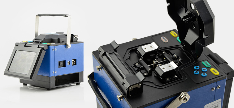
Fusion splicing has been the de facto standard for fiber feeder and distribution construction networks. Fusion splicer is used for FTTH drop splicing as it provides a high quality splice with low insertion loss and reflection. However, the initial capital expenditures, maintenance costs and slow installation speed of fusion splicing hinder its status as the preferred solution. Fusion splicing is suitable for companies which have invested in fusion splicing equipment and have no need to purchase additional splicing machines. Mechanical splices are successfully deployed around the world in FTTH installation, but not popular in United States because the index matching gel inside the splices can yellow or dry out, resulting in service failures. Great strides have been made in improving gel performance and longevity over the last 20 years.
Connectors could be used to connect different subscribers as needed for distribution points. It must be installed at the ONT and then offers flexibility both at the curb and at the home. Once the decision goes to connectors, factory-terminated connectors or field-terminated connectors must be decided.
Factory-terminated cables, such as LC to LC cable or SC to LC cable, which means the connectors you specify are pre-terminated for you, provide high-performance and reliable connections with low optical loss. By reducing installation time, factory termination keeps labor costs low. But factory-terminated cables are expensive compared to field-terminated alternatives. And they require a cable management system to store slack cable at the curb or in home. The installation of field-terminated connectors can be customized by using a reel of cable and connectors. Fuse-on connectors use the same technology as fusion splicing to provide the highest level of optical performance in a field-terminated connector. Mechanical connectors provide alternatives to fuse-on connectors for field installation of drop cables. Depending upon service provider requirements and living unit configurations, a hybrid solution of a field-terminated connector on one end of the drop cable and a factory-terminated connector on the other may be the optimal solution.
Choosing the right drop cable interconnect solution is a key and important step for a successful FTTH network deployment. Making the right connection option will not only offer cost savings and efficient deployment but also provide reliable service for customers. Splices and connectors are two options for you. They have their advantages and disadvantages. A better understanding of them two can help you make a more suitable choice.
Posted by: jowang at
02:42 AM
| No Comments
| Add Comment
Post contains 853 words, total size 7 kb.
32 queries taking 0.0769 seconds, 90 records returned.
Powered by Minx 1.1.6c-pink.

